- English
- Nederlands
Custom Ship Propeller
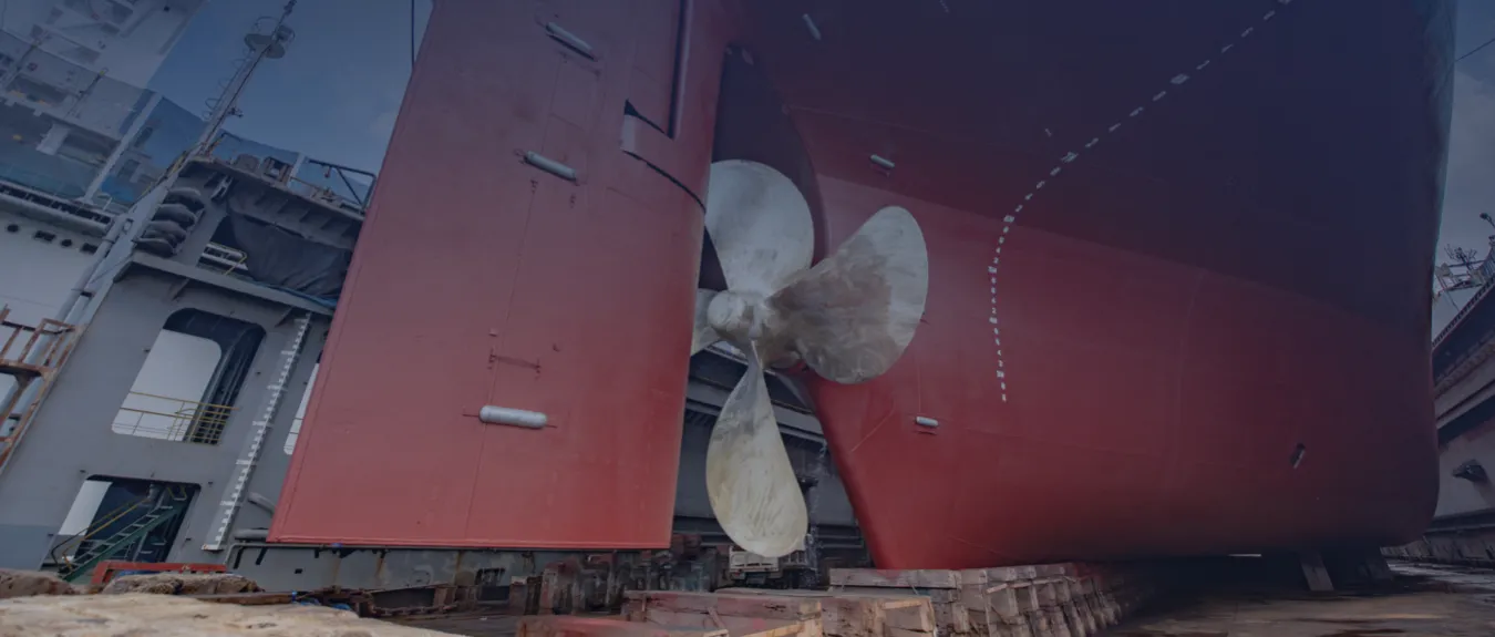
A ship propeller is the primary propulsion component in a ship propulsion system that converts rotational shaft power into thrust, influencing propulsion efficiency, cavitation behaviour, vibration, underwater noise and fuel consumption. For a custom ship propeller, the flow around the hull and propeller is digitally analysed with Computational Fluid Dynamics (CFD), comparable to physical model testing. Based on that analysis, performance under representative conditions can be predicted and the design can be aligned with hull form, rudder systems, appendages such as the propeller nozzle, the drivetrain and the operational profile. In collaboration with our international partner, we assist with the design and delivery of the appropriate ship propeller for newbuilds and retrofits, tailored to your ship type and operational profile.
Available worldwide
Propeller Performance And Approval
For shipping companies and shipowners, a propeller that is seamlessly matched to ship type and operational profile can lead to lower fuel consumption, fewer emissions and reduced cavitation, vibration and maintenance. The eventual gains differ per operational profile, but an optimized propeller design also supports compliance with the Energy Efficiency Existing Ship Index (EEXI) and the Carbon Intensity Indicator (CII). After formal acceptance by the competent authorities, the technical substantiation towards the European Union Emissions Trading System (EU ETS) and FuelEU Maritime is simplified.
The delivery programme includes Fixed Pitch Propellers (FPP), blades for Controllable Pitch Propellers (CPP), propeller nozzles, bow thrusters, propellers for azimuth thrusters and electric pods.
As a starting point for the choice between, for example, a Fixed Pitch Propeller (FPP) and a propeller nozzle, Ship Propeller Types and Propulsion Configurations provides the required overview.
Propeller Design Process
Designing an efficient, low-noise or robust propeller starts with a clearly defined propulsion concept, aligned with the operational requirements of the ship and the segment, whether newbuild or retrofit. Computational Fluid Dynamics (CFD) forms the digital basis of the propeller design and substantiates choices that, depending on the operational profile, are aimed at efficiency, noise reduction and robustness. Which objective has priority is project specific and determines the design choices in the subsequent steps. The complete approach from concept to blade geometry and material is set out in Ship Propeller Design and Optimization.
In practice, efficiency, noise reduction and robustness form a design triangle with inherent trade-offs. Prioritizing additional robustness often leads to greater blade thicknesses, different alloys or protective provisions, which increase mass and wetted area and can reduce efficiency and acoustic performance at cruising speed. Conversely, a design that minimizes resistance is less forgiving of damage or erosion. Therefore, for each project, the priority objective and the conditions for optimization are explicitly recorded, so that the trade-off remains transparent and verifiable.
Within that context, priorities differ by ship type. Inland vessels on European waterways often require propellers that remain efficient and predictable at low speed and with frequent manoeuvres, with tolerance for limited draught. Offshore support vessels (OSVs) generally value operational reliability and direct response in rough seas, with emphasis on cavitation margin and stable behaviour during station keeping. Dredgers and trawlers typically select robust, erosion-tolerant propellers with high thrust at low speed. Other ship types, such as coastal vessels, oil tankers and bulk carriers, primarily optimize for low fuel consumption over long legs, with efficiency at cruising speed as the leading criterion. Ferries usually prioritize low noise and vibration levels and finely controllable thrust for passenger comfort and port approaches. Finally, naval vessels often prioritize manoeuvrability, a low underwater noise signature and operational discretion, with strict cavitation control across a wide load range.
The propeller design is then aligned integrally with the hull and afterbody, appendages (nozzle, rudder), the drivetrain and the reversing gear or gearbox. Depending on the propulsion concept, from conventional diesel drivetrains to electric or hybrid systems, the design targets high efficiency within the relevant speed and draught range. If robustness has priority, the focus shifts to cavitation margin, tip and clearance margins in the nozzle, attachment details and maintenance accessibility. This system interaction forms the basis for the CFD analysis and the subsequent numerical optimization.
For performance prediction, the flow around the hull and propeller is analysed with CFD. This method, standard in shipbuilding, enables detailed calculations and realistic speed predictions already in the design phase. If the simulations show that the available power is insufficient, targeted modifications to, for example, the bulbous bow or the afterbody come into view. Where necessary, erosion-prone zones and local load peaks are reduced, so that robustness is preserved in service. How simulations, cavitation research, model tests and onboard measurements in accordance with ISO standards together form the validation chain is set out in Ship Propeller Validation, CFD and Performance Measurement.
A crucial step is the choice of blade count in conjunction with diameter and pitch. These parameters govern the balance between efficiency, thrust, smooth running and service life. The calculations enable our partner to provide substantiated advice on the configuration that suits the ship type and the operational conditions. Material selection is also a factor. In Arctic waters, impact toughness and resistance to low temperatures usually carry more weight, while on tropical routes corrosion resistance and cavitation-erosion resistance are decisive. In this way, each design choice remains explicitly linked to the intended deployment profile and the required operational reliability.
Finally, formal alignment with ice class and classification follows. Depending on the operating conditions and the client’s requirements, the design is aligned with the required ice class and with the guidelines of classification societies such as DNV (formerly Det Norske Veritas), Lloyd’s Register (LR), American Bureau of Shipping (ABS), Bureau Veritas (BV) and Registro Italiano Navale (RINA). The intended result is a propeller designed for the relevant operating conditions which, with the required documentation and approval, meets the international frameworks of the International Maritime Organization (IMO). Certification and approval take place after acceptance by the classification society.
Technical Characteristics And Material Selection Of Propellers
The choice of propeller, including blade geometry and material selection, largely determines performance, durability and noise generation. The delivery programme includes configurations with three to seven blades, diameters of approximately 30 to 160 inches (approximately 0.7 to 4.0 metres) and masses up to approximately 12 tonnes. Which configuration is most suitable depends on the operational profile, the available installation space and the requirements of the classification society, so that the eventual propeller design is precisely aligned with the intended deployment and operating conditions.
Material selection is a second determining factor. Nickel-aluminium bronze (CuNiAl, often Cu3) is widely used due to its favourable combination of cavitation-erosion resistance and corrosion resistance in seawater. Under cavitation loading, Cu3 can harden locally, so damage often remains limited to repairable pitting. Where the operational loading is less extreme, manganese bronze (Cu1) offers an attractive alternative with a balanced ratio between strength, service life and cost, often on ships that are not continuously exposed to aggressive seawater. In situations with higher mechanical demands or specific conditions, stainless steel (SS) can provide a solution, for example CF3, an austenitic stainless-steel cast grade. This material stands out for tensile strength and wear resistance. However, SS usually requires careful cathodic protection and periodic maintenance, because in this application it can be more sensitive to cavitation erosion than Cu3 alloys. The implications for maintenance and service life and the effect on frameworks such as EEXI/CII, the EU ETS and FuelEU Maritime are set out in Ship Propeller Life Cycle, Retrofit and Regulatory Framework.
In addition to material, geometric parameters steer propulsion performance. Blade count, diameter and pitch together determine the balance between efficiency, thrust and smooth running. A larger disc area increases the cavitation margin and can limit vibration; a lower blade count reduces friction losses under favourable inflow conditions. In this way, efficiency remains high in diverse operating situations, without compromising robustness or comfort.
Subtler design choices govern the hydrodynamics. Skew, the aftward curvature of the blades, spreads cavitation and can markedly reduce vibration. Rake, the inclination relative to the propeller axis, supports stable performance at varying draught and inflow conditions. Tip geometry, the shape of the blade tips, also influences vortex formation and directly affects efficiency and noise generation. On passenger ships, research vessels and naval vessels, Underwater Radiated Noise (URN) usually carries significant weight. A suitable blade design supports internal URN objectives and can, where relevant, align with guidelines such as ICES 209. In this way, design choices for comfort, operational reliability and compliance remain consistently substantiated and traceable.
Optimization Of Existing Vessels With A New Propeller
When an existing ship is due for propeller replacement, an optimized design can, depending on hull condition and deployment profile, noticeably improve performance. If the original drawings of the ship and propeller are available, that dataset forms the starting point. The custom design aligns geometrically with the afterbody, shaft line, nozzle and rudder and is tuned to the intended operational profile, so that all design choices remain traceable.
If the drawings are missing, that is not a barrier. The afterbody is captured accurately with a 3D scan, supplemented with targeted measurements of, among other things, tip and clearance margins, shaft centreline height and appendages. That digital hull geometry forms the basis for Computational Fluid Dynamics (CFD), with which the flow around the propeller is simulated under representative conditions and design variants can be compared under identical conditions. Based on that analysis, a retrofit design emerges that fits both technically and operationally.
The result is a single or twin propeller configuration designed for the relevant operating conditions of the ship. In practice, depending on operating behaviour, loading and maintenance conditions, this can lead to higher propulsion efficiency, lower emissions and reduced cavitation and vibration, with positive effects on maintenance and comfort.
Controllable Pitch Blades (CPP Blades)
A Controllable Pitch Propeller (CPP) makes it possible to vary blade pitch while under way. Compared to a Fixed Pitch Propeller (FPP), torque and rotational speed can therefore be matched more precisely to changing operating conditions. That improves manoeuvrability and makes propulsion behaviour across different speed regimes more finely controllable, provided the pitch control is correctly aligned with engine and load characteristics.
In practice, that flexibility is especially relevant with frequent course or speed changes. Ferries and offshore support vessels benefit from rapid torque build-up and precise speed control during port approaches and station keeping. Naval vessels often place extra emphasis on response, low noise levels and predictable behaviour at part load. At the same time, an FPP can be more favourable in terms of simplicity and maintenance at long, steady cruising speed. The choice depends on operational profile, propulsion concept and the desired controllability.
Controllable Pitch Propeller blades (CPP blades) can, regardless of the original brand, be digitally measured, reproduced one-to-one and optimized if desired. If hub geometry and pitch actuation kinematics fall within the existing type approval, the blade profile can be adjusted in detail to limit cavitation-prone zones and refine part-load performance. Computational Fluid Dynamics (CFD) substantiates these trade-offs by comparing variants under equal conditions. The eventual optimization depends on installation space, hub geometry, pitch actuation kinematics and the intended operating regime.
On existing installations, newly manufactured CPP blades can extend the service life of the propulsion system without far-reaching system modifications. With CFD substantiation, a transparent rationale arises for design and material choices, in particular around blade profile, skew and tip geometry. Certification and approval take place after acceptance by the classification society.
Custom Ship Propeller
In collaboration with our international partner, we assist with the design and delivery of the appropriate ship propeller for newbuilds and retrofits, tailored to your ship type and operational profile.

Available worldwide
What Is a Ship Propeller?
A ship propeller is the primary propulsion component in a ship propulsion system that converts rotational shaft power into thrust, influencing propulsion efficiency, cavitation behaviour, vibration, underwater noise and fuel consumption.
For a custom ship propeller, the flow around the hull and propeller is digitally analysed with Computational Fluid Dynamics (CFD), comparable to physical model testing.
Based on that analysis, performance under representative conditions can be predicted and the design can be aligned with hull form, rudder systems, appendages such as the propeller nozzle, the drivetrain and the operational profile.
Propeller Performance And Approval
For shipping companies and shipowners, a propeller that is seamlessly matched to ship type and operational profile can lead to lower fuel consumption, fewer emissions and reduced cavitation, vibration and maintenance. The eventual gains differ per operational profile, but an optimized propeller design also supports compliance with the Energy Efficiency Existing Ship Index (EEXI) and the Carbon Intensity Indicator (CII). After formal acceptance by the competent authorities, the technical substantiation towards the European Union Emissions Trading System (EU ETS) and FuelEU Maritime is simplified.
The delivery programme includes Fixed Pitch Propellers (FPP), blades for Controllable Pitch Propellers (CPP), propeller nozzles, bow thrusters, propellers for azimuth thrusters and electric pods.
As a starting point for the choice between, for example, a Fixed Pitch Propeller (FPP) and a propeller nozzle, Ship Propeller Types and Propulsion Configurations provides the required overview.
Propeller Design Process
Designing an efficient, low-noise or robust propeller starts with a clearly defined propulsion concept, aligned with the operational requirements of the ship and the segment, whether newbuild or retrofit. Computational Fluid Dynamics (CFD) forms the digital basis of the propeller design and substantiates choices that, depending on the operational profile, are aimed at efficiency, noise reduction and robustness. Which objective has priority is project specific and determines the design choices in the subsequent steps. The complete approach from concept to blade geometry and material is set out in Ship Propeller Design and Optimization.
In practice, efficiency, noise reduction and robustness form a design triangle with inherent trade-offs. Prioritizing additional robustness often leads to greater blade thicknesses, different alloys or protective provisions, which increase mass and wetted area and can reduce efficiency and acoustic performance at cruising speed. Conversely, a design that minimizes resistance is less forgiving of damage or erosion. Therefore, for each project, the priority objective and the conditions for optimization are explicitly recorded, so that the trade-off remains transparent and verifiable.
Within that context, priorities differ by ship type. Inland vessels on European waterways often require propellers that remain efficient and predictable at low speed and with frequent manoeuvres, with tolerance for limited draught. Offshore support vessels (OSVs) generally value operational reliability and direct response in rough seas, with emphasis on cavitation margin and stable behaviour during station keeping. Dredgers and trawlers typically select robust, erosion-tolerant propellers with high thrust at low speed. Other ship types, such as coastal vessels, oil tankers and bulk carriers, primarily optimize for low fuel consumption over long legs, with efficiency at cruising speed as the leading criterion. Ferries usually prioritize low noise and vibration levels and finely controllable thrust for passenger comfort and port approaches. Finally, naval vessels often prioritize manoeuvrability, a low underwater noise signature and operational discretion, with strict cavitation control across a wide load range.
The propeller design is then aligned integrally with the hull and afterbody, appendages (nozzle, rudder), the drivetrain and the reversing gear or gearbox. Depending on the propulsion concept, from conventional diesel drivetrains to electric or hybrid systems, the design targets high efficiency within the relevant speed and draught range. If robustness has priority, the focus shifts to cavitation margin, tip and clearance margins in the nozzle, attachment details and maintenance accessibility. This system interaction forms the basis for the CFD analysis and the subsequent numerical optimization.
For performance prediction, the flow around the hull and propeller is analysed with CFD. This method, standard in shipbuilding, enables detailed calculations and realistic speed predictions already in the design phase. If the simulations show that the available power is insufficient, targeted modifications to, for example, the bulbous bow or the afterbody come into view. Where necessary, erosion-prone zones and local load peaks are reduced, so that robustness is preserved in service. How simulations, cavitation research, model tests and onboard measurements in accordance with ISO standards together form the validation chain is set out in Ship Propeller Validation, CFD and Performance Measurement.
A crucial step is the choice of blade count in conjunction with diameter and pitch. These parameters govern the balance between efficiency, thrust, smooth running and service life. The calculations enable our partner to provide substantiated advice on the configuration that suits the ship type and the operational conditions. Material selection is also a factor. In Arctic waters, impact toughness and resistance to low temperatures usually carry more weight, while on tropical routes corrosion resistance and cavitation-erosion resistance are decisive. In this way, each design choice remains explicitly linked to the intended deployment profile and the required operational reliability.
Finally, formal alignment with ice class and classification follows. Depending on the operating conditions and the client’s requirements, the design is aligned with the required ice class and with the guidelines of classification societies such as DNV (formerly Det Norske Veritas), Lloyd’s Register (LR), American Bureau of Shipping (ABS), Bureau Veritas (BV) and Registro Italiano Navale (RINA). The intended result is a propeller designed for the relevant operating conditions which, with the required documentation and approval, meets the international frameworks of the International Maritime Organization (IMO). Certification and approval take place after acceptance by the classification society.
Technical Characteristics And Material Selection Of Propellers
The choice of propeller, including blade geometry and material selection, largely determines performance, durability and noise generation. The delivery programme includes configurations with three to seven blades, diameters of approximately 30 to 160 inches (approximately 0.7 to 4.0 metres) and masses up to approximately 12 tonnes. Which configuration is most suitable depends on the operational profile, the available installation space and the requirements of the classification society, so that the eventual propeller design is precisely aligned with the intended deployment and operating conditions.
Material selection is a second determining factor. Nickel-aluminium bronze (CuNiAl, often Cu3) is widely used due to its favourable combination of cavitation-erosion resistance and corrosion resistance in seawater. Under cavitation loading, Cu3 can harden locally, so damage often remains limited to repairable pitting. Where the operational loading is less extreme, manganese bronze (Cu1) offers an attractive alternative with a balanced ratio between strength, service life and cost, often on ships that are not continuously exposed to aggressive seawater. In situations with higher mechanical demands or specific conditions, stainless steel (SS) can provide a solution, for example CF3, an austenitic stainless-steel cast grade. This material stands out for tensile strength and wear resistance. However, SS usually requires careful cathodic protection and periodic maintenance, because in this application it can be more sensitive to cavitation erosion than Cu3 alloys. The implications for maintenance and service life and the effect on frameworks such as EEXI/CII, the EU ETS and FuelEU Maritime are set out in Ship Propeller Life Cycle, Retrofit and Regulatory Framework.
In addition to material, geometric parameters steer propulsion performance. Blade count, diameter and pitch together determine the balance between efficiency, thrust and smooth running. A larger disc area increases the cavitation margin and can limit vibration; a lower blade count reduces friction losses under favourable inflow conditions. In this way, efficiency remains high in diverse operating situations, without compromising robustness or comfort.
Subtler design choices govern the hydrodynamics. Skew, the aftward curvature of the blades, spreads cavitation and can markedly reduce vibration. Rake, the inclination relative to the propeller axis, supports stable performance at varying draught and inflow conditions. Tip geometry, the shape of the blade tips, also influences vortex formation and directly affects efficiency and noise generation. On passenger ships, research vessels and naval vessels, Underwater Radiated Noise (URN) usually carries significant weight. A suitable blade design supports internal URN objectives and can, where relevant, align with guidelines such as ICES 209. In this way, design choices for comfort, operational reliability and compliance remain consistently substantiated and traceable.
Optimization Of Existing Vessels With A New Propeller
When an existing ship is due for propeller replacement, an optimized design can, depending on hull condition and deployment profile, noticeably improve performance. If the original drawings of the ship and propeller are available, that dataset forms the starting point. The custom design aligns geometrically with the afterbody, shaft line, nozzle and rudder and is tuned to the intended operational profile, so that all design choices remain traceable.
If the drawings are missing, that is not a barrier. The afterbody is captured accurately with a 3D scan, supplemented with targeted measurements of, among other things, tip and clearance margins, shaft centreline height and appendages. That digital hull geometry forms the basis for Computational Fluid Dynamics (CFD), with which the flow around the propeller is simulated under representative conditions and design variants can be compared under identical conditions. Based on that analysis, a retrofit design emerges that fits both technically and operationally.
The result is a single or twin propeller configuration designed for the relevant operating conditions of the ship. In practice, depending on operating behaviour, loading and maintenance conditions, this can lead to higher propulsion efficiency, lower emissions and reduced cavitation and vibration, with positive effects on maintenance and comfort.
Controllable Pitch Blades (CPP Blades)
A Controllable Pitch Propeller (CPP) makes it possible to vary blade pitch while under way. Compared to a Fixed Pitch Propeller (FPP), torque and rotational speed can therefore be matched more precisely to changing operating conditions. That improves manoeuvrability and makes propulsion behaviour across different speed regimes more finely controllable, provided the pitch control is correctly aligned with engine and load characteristics.
In practice, that flexibility is especially relevant with frequent course or speed changes. Ferries and offshore support vessels benefit from rapid torque build-up and precise speed control during port approaches and station keeping. Naval vessels often place extra emphasis on response, low noise levels and predictable behaviour at part load. At the same time, an FPP can be more favourable in terms of simplicity and maintenance at long, steady cruising speed. The choice depends on operational profile, propulsion concept and the desired controllability.
Controllable Pitch Propeller blades (CPP blades) can, regardless of the original brand, be digitally measured, reproduced one-to-one and optimized if desired. If hub geometry and pitch actuation kinematics fall within the existing type approval, the blade profile can be adjusted in detail to limit cavitation-prone zones and refine part-load performance. Computational Fluid Dynamics (CFD) substantiates these trade-offs by comparing variants under equal conditions. The eventual optimization depends on installation space, hub geometry, pitch actuation kinematics and the intended operating regime.
On existing installations, newly manufactured CPP blades can extend the service life of the propulsion system without far-reaching system modifications. With CFD substantiation, a transparent rationale arises for design and material choices, in particular around blade profile, skew and tip geometry. Certification and approval take place after acceptance by the classification society.
Propellers In Practice
Projects with Fixed Pitch Propellers (FPP), propeller nozzles, Controllable Pitch Propeller (CPP) blades, bow thrusters, propellers for azimuth thrusters and electric pods demonstrate that a CFD-substantiated design, aligned with the hull, drivetrain and operational profile, can lead to more efficient propulsion and lower emissions. Applications range from inland and coastal shipping to seagoing shipping and extend to dredging, offshore, fisheries and navy. Depending on the function in the propulsion system, main propulsion or manoeuvring at low speed, lower fuel consumption and reduced CO2 emissions are possible under representative conditions. The eventual gains are related to loading, operational behaviour and maintenance.