
- English
- Nederlands

Energy Saving Devices (ESDs) for Shipping
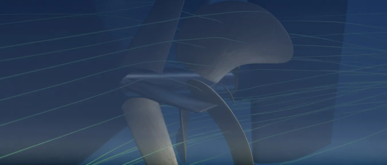
Energy Saving Devices (ESDs) are hydrodynamic devices that influence the flow ahead of, around and behind the ship’s propeller to reduce propulsion losses. Better interaction between the hull, propeller and rudder can reduce the power required at the same ship speed. For shipowners, this offers opportunities to reduce fuel consumption, fuel costs and CO2 emissions. However, not every device delivers the same benefit on every ship. Selection depends on the flow field around the propeller, propeller loading and the speeds and loading conditions in which the ship operates. The available installation space, the drag of the ESD itself and possible effects on cavitation, vibration and rudder performance also play a part. In cooperation with a specialist international partner, we support the assessment, selection, engineering, integration and implementation of the Pre-Swirl Stator (PSS), Pre-Duct, Propeller Boss Cap Fins (PBCF) and Rudder Bulb for existing ships and newbuild projects.
Available worldwide
Where Do Losses Occur Around the Propeller?
The water does not reach every part of the propeller at the same speed and in the same direction. The hull, stern and existing appendages have already influenced the flow by that point. As a result, a non-uniform flow field develops across the propeller plane, known as the wake field. During each revolution, the propeller blades move through this field, causing their inflow and loading to change continuously.
The propeller converts the supplied shaft power into thrust by accelerating water. Energy remains in the propeller slipstream, including in rotation and vortex structures. Frictional losses also occur. Some acceleration of the water is unavoidable to generate sufficient thrust. The opportunities for improvement lie mainly in losses that can be reduced through more favourable flow and better interaction between the propulsion components.
A local improvement is not, however, automatically an improvement in overall propulsion. If the wake field changes, the pressure distribution on the stern and the forces on the propeller, rudder and added components may also change. An ESD must therefore be assessed in terms of its influence on the total shaft power needed to maintain the same ship speed.
Pre-Swirl Stator and Pre-Duct as Solutions Ahead of the Propeller
A Pre-Swirl Stator (PSS) consists of fixed fins that are positioned ahead of the propeller. These give the incoming water a controlled rotation in the opposite direction to propeller rotation. As a result, the relative inflow to the propeller blades changes, and less rotational energy may remain in the final propeller slipstream.
The fins have a shape and setting based on the local flow and the characteristics of the propeller. Excessive or incorrectly directed pre-swirl may actually limit the intended improvement. The stator itself also causes drag, and the rotating propeller influences the flow around the fins. The design therefore focuses on the combined performance of the stator and propeller, not solely on generating as much pre-swirl as possible.
A Pre-Duct operates on a different principle. This flow-guiding duct is positioned ahead of the propeller plane and influences the direction and speed distribution of the water reaching the propeller. In this respect, the device differs from a nozzle, which surrounds the propeller. The forces on the Pre-Duct itself also matter. Depending on the pressure distribution and geometry, the duct may provide a favourable force in the direction of travel, but may also cause additional drag.
Where both flow guidance and pre-swirl can offer improvement, a duct and stator fins can be combined. Their operation is then not independent: the duct changes the inflow to the fins, while both together determine how the water reaches the propeller. A comparison of individual and combined designs shows which design offers the greatest promise for the propulsion configuration concerned.
PBCF and Rudder Bulb Behind the Propeller
Energy can also be lost behind the propeller. The hub vortex and the flow between the propeller hub and rudder offer particular opportunities for targeted optimization. A device on the rotating boss cap influences this region differently from a component on the stationary rudder.
Propeller Boss Cap Fins (PBCF) consist of small fins on the cap behind the propeller hub. The fins rotate with the propeller and influence the flow around the hub and the formation of the hub vortex. Thrust and the required torque may thus improve. The outcome depends strongly on the shape of the fins, their position relative to the propeller blades and the geometry of the boss cap.
A weaker hub vortex does not in itself mean that the propeller operates more efficiently. The combined thrust and torque of the propeller and hub device matter for the performance comparison. An unfavourable design may cause additional losses, even where the local flow pattern changes.
A Rudder Bulb is a streamlined enlargement of the rudder at the level of the propeller hub. It influences the flow transition between the boss cap and rudder. The distance between them, their alignment and their shape partly determine how pressure is distributed in this region. A well-matched bulb can reduce losses, but must also suit the geometry and operation of the rudder.
A PBCF and Rudder Bulb can be used individually or together. Their combination does not, however, automatically yield the sum of the two individual improvements. Both devices may affect some of the same losses. The additional contribution that the second device still makes is therefore investigated, along with whether the required space between the components is maintained.
Twisted Rudder as Additional Rudder Optimization
Alongside the four primary ESD solutions, the rudder profile itself can also be modified. A Twisted Rudder accounts for the different inflow directions that arise from the rotating propeller slipstream. For this purpose, the profile is varied over its height so that the local inflow better matches the shape of the rudder.
A more favourable angle of attack can reduce rudder drag and local low-pressure regions. Cavitation and the associated vibration may also decrease as a result. The extent of the benefit depends on the design and the flow behind the propeller concerned.
A rudder must, however, do more than produce little drag during straight-ahead operation under ideal conditions. The required steering performance and loads at other speeds and rudder angles remain decisive for the design.
A Twisted Rudder can be developed separately or combined with, for example, a Rudder Bulb. The suitable design follows from the interaction between the propeller, boss cap, bulb and rudder. The result is assessed in terms of propulsion performance and steering performance under the operating conditions in which the ship is used.
Why the Right ESD Differs from Ship to Ship
An ESD that performs well on one ship need not deliver the same saving on a similar ship. Even with comparable principal dimensions, differences in stern shape, shaft arrangement and propeller and rudder positions may produce a different wake field. Existing appendages and the available space around the propulsion system also influence the possibilities.
The operational profile then determines where the improvement has the greatest value. A ship that operates for long periods at roughly constant speed and loading may require different optimization from a ship whose speed, draught and propeller loading vary considerably. The selected device must therefore perform particularly well under the operating conditions that carry the greatest weight in service.
For a Controllable Pitch Propeller (CPP), a propeller with adjustable pitch, the combinations of blade pitch and rotational speed used are also examined. The geometry and technical condition of the CPP blades influence blade loading and flow. For a PBCF or other hub device, the specific hub construction and the adjustment range of the blades also matter. A design for a fixed pitch propeller therefore cannot simply be applied to a CPP.
Sometimes it becomes apparent that the first improvement does not come from an ESD. Fouling, damaged propeller blades or a propeller poorly matched to the current operational profile may already have a substantial effect on power demand. There is little point in optimizing a new device for a starting condition that will soon change through maintenance or another modification.
A reliable comparison therefore starts with the intended condition and configuration of the ship. From there, whether an ESD is the right next step and which configuration suits the propulsion system can be investigated.
Assessing Multiple ESDs as One Propulsion Configuration
When several ESDs are combined, each device changes the flow in which the next must operate. A Pre-Swirl Stator, for example, influences the inflow to the propeller and therefore also the propeller slipstream reaching the rudder. A PBCF or Rudder Bulb operates differently in that modified flow than it does without a stator.
Some devices complement each other, while others address partly the same losses. Adverse interactions can also arise. Two separately calculated savings must therefore not simply be added together. The additional contribution of each device is investigated within the configuration in which it is actually used.
Changes to the propeller or rudder can also influence the optimum shape and position of an ESD. A combined design can therefore offer more than optimizing existing components individually. Conversely, it may become apparent from the same analysis that a single device is sufficient and that further additions offer hardly any extra benefit.
The number of ESDs does not determine the quality of the solution, but the combined propulsion performance and practical integration on board do.
CFD as a Basis for Design and Comparison
With Computational Fluid Dynamics (CFD), the flow around the hull, propeller and rudder can be investigated before an ESD is manufactured. The calculations show where losses occur and how changes in geometry influence the flow, forces and power demand. For this purpose, the existing or planned propulsion configuration is first defined as the reference.
Next, ESD design variants are compared using CFD in terms of their combined propulsion performance. A useful comparison requires more than entering the same speed or the same propeller rotational speed. Each configuration must provide sufficient thrust to propel the ship at the selected speed. The required rotational speed and torque may change in the process.
A variant that provides more thrust at the same rotational speed is therefore not automatically the variant that requires less shaft power at the same ship speed. To reach that conclusion, the full propulsion balance must be compared, including the forces on the added components and the changed interaction with the hull and rudder.
How detailed the flow model must be varies with the design question. For a Pre-Swirl Stator, the local inflow and interaction with the rotating propeller are important. For a PBCF, it is the flow around the blade roots, boss cap and hub vortex that requires particular attention. A simplified representation of the propeller may be useful for an initial investigation, but it must retain the interactions that govern the design choice in question.
The numerical reliability of the calculations also warrants attention. The sensitivity of the results to spatial discretization can be investigated by refining the computational mesh. In time-dependent calculations, the influence of the time step is also examined. The predicted forces and power levels must be sufficiently stable for a meaningful comparison between design variants.
A numerically stable result is, however, still not proof that the actual flow is accurately predicted. For this, a comparison with suitable measurements is needed. Model tests can provide valuable information about the flow and propulsion performance, but they also introduce scale differences that may be relevant to ESDs.
At model scale, the boundary layer, wake field and flow around propeller blades and fins do not develop under exactly the same conditions as at full scale. A general scale correction therefore does not necessarily describe the behaviour of every ESD configuration. Calculations at full ship scale can help investigate these differences, but remain dependent on the selected geometry, surface condition and flow models.
The final design decision does not depend solely on which variant has the lowest predicted power. The size of the difference and the uncertainty in the calculation are also important. When two designs perform almost equally, a small calculated advantage may be insufficient to justify the choice on its own.
A convincing preferred variant therefore combines a sufficiently substantiated performance improvement with a usable operating range and feasible integration into the ship.
Cavitation, Vibration and Rudder Performance
A lower power demand is not sufficient if the modified flow causes new problems. An ESD changes the pressure distribution around the propeller, the rudder and the device itself. If the local pressure falls sufficiently, water vapour can form. This phenomenon is called cavitation. The collapse of the resulting vapour bubbles can cause pressure fluctuations, noise and erosion.
The propeller is not the only component that can be affected in this way. Stator fins, duct profiles and parts of the rudder may also experience locally unfavourable pressures or fluctuating loads. The assessment therefore covers the relevant rotational speeds, loading conditions and rudder angles.
An ESD that performs favourably when the ship is sailing straight ahead must also remain compatible with steering performance and the loads under other operating conditions. In this way, a local hydrodynamic improvement is prevented from coming at the expense of the wider operational characteristics of the ship.
From Hydrodynamic Design to Structural Integration
A sound flow design must also be structurally feasible. Stator fins and Pre-Ducts transfer their forces through the attachments to the hull and the structure behind it. For a Rudder Bulb, the load on the rudder blade and the consequences for the rudder installation also play a part. A PBCF, by contrast, rotates with the propeller and must fit the rotating hub structure.
The method known internationally as the Finite Element Method (FEM) can be used to investigate stresses, deformations and the dynamic behaviour of these components. The loads must correspond to the hydrodynamic configuration that is actually built. In addition to mean forces, fluctuating loads from passing propeller blades and ship motions may be relevant.
Strength and fatigue require separate attention. A component may safely withstand a high load once, yet still suffer damage through prolonged repetition. The natural frequencies of a structure may also be important if they coincide unfavourably with periodic loading from the propeller.
Material selection, attachments and provisions for inspection are developed in accordance with the applicable requirements of the classification society and other competent authorities. The required space between the propeller, hub device and rudder must be maintained, including when components deform or move under load.
Structural approval and hydrodynamic performance verification serve different purposes. A safe, correctly installed ESD does not automatically deliver the predicted fuel saving.
Energy Saving Devices in Retrofit and Newbuild Projects
In retrofit projects, the greatest challenge often lies in improving propulsion without major changes to the existing installation. The hull, propeller shaft, propeller and rudder arrangement are largely fixed. Within those limits, a purpose-designed ESD can still offer an improvement.
The assessment therefore covers structural integration, maintenance throughout the service life and applicable regulations from the outset. This prevents a hydrodynamically promising design from encountering structural or implementation constraints only at a later stage.
For installation, the available drawings must correspond sufficiently closely to the actual condition on board. Attachment points, structural space and accessibility help determine how installation can take place. Production, any steelwork, coating work and verification of the final positioning are then coordinated with the docking schedule.
A scheduled docking offers opportunities to combine work. Even so, an ESD may require additional preparation or yard time, particularly where structural modifications or additional checks are needed. These consequences form part of the balance between expected savings and project costs.
In newbuild projects, there is greater design freedom. The stern, propeller, rudder and ESD can be developed together at an early stage, allowing their geometry and relative positions to match more closely. The contribution of the ESD is then compared with the selected base configuration. Improvements to the main design and the additional effect of the device are not counted twice.
From Power Reduction to Fuel Saving
For a shipowner, what ultimately matters is how much fuel an ESD can save during operation. A lower power demand is the starting point, but it does not determine the fuel benefit on its own. Engine load, efficiency and the way in which the ship uses the improvement also play a part.
At the same ship speed, a lower shaft power requirement can lead to lower fuel consumption. If the available power is instead used to sail faster, a different outcome results. An estimate of savings must therefore reflect the speed and operation for which the investment is being considered.
The hydrodynamic comparison covers the forces on the ESD and the changed interaction between the hull, propeller and rudder. How the lower power demand affects propeller rotational speed, engine load and fuel consumption is then calculated. For a CPP, the relevant combinations of rotational speed and blade pitch are also included.
An improvement in propulsion efficiency does not automatically represent the same percentage fuel saving. It also makes a difference whether the stated figure concerns propulsion alone or total ship consumption. After all, the electricity demand of other onboard installations remains, even when the propeller requires less power.
The savings estimate therefore has a clear system boundary. It is then clear which energy flows change and which part of fuel consumption remains outside the influence of the ESD.
For an annual forecast, performance is weighted according to the operating hours at different speeds, draughts and loading conditions. An anticipated change in the use of the ship also belongs in that calculation. The most favourable design operating point is therefore not automatically representative of the entire operation.
Comparing Calculated and Measured ESD Performance
When an ESD is installed, the hydrodynamic characteristics of the ship change. A reliable reference is needed to assess later what the modification has actually achieved. The original geometry, hull and propeller condition, and available operating data together form the starting point.
Particularly in retrofit projects, it can be difficult to attribute a performance improvement solely to the ESD. During the same docking, the hull is often also cleaned, coatings are renewed or work is carried out on the propeller. Each of these interventions can influence power demand. Moreover, a permanently installed ESD cannot simply be switched off during a sea trial to allow direct comparison with the same ship configuration without an operating ESD.
A lower measured power after docking therefore does not in itself prove how much of the reduction was caused by the ESD.
CFD and model tests help determine the expected effects in advance. Onboard measurements then show how the ship performs under the conditions investigated. The comparison requires data on speed, propeller shaft rotational speed, torque and fuel consumption, among other variables, supplemented by draught, trim and environmental conditions.
Speed through the water must be distinguished from speed over the ground. Current can change speed over the ground without the flow along the hull changing to the same extent. Wind and waves may also require additional propulsion power. If such differences are not sufficiently accounted for, the measured performance difference may be misinterpreted.
The accuracy and comparability of the data are also decisive. The expected ESD effect must be sufficiently distinguishable from measurement uncertainty and changes in conditions. A short sea trial can provide insight into a limited number of operating points, but does not automatically describe performance across the full operational profile.
For a broader assessment, sea trial results are therefore linked to additional calculations or operational data. It remains clear which results have actually been measured and which have been predicted.
The evidence required depends on the purpose. A well-substantiated comparison of configurations may be sufficient for a design decision. Contractual performance agreements require references, measurement methods, uncertainty assessment and acceptance criteria agreed in advance. For formal energy efficiency calculations, the applicable calculation and verification rules also apply.
Maintenance and Changes During Service Life
After installation, an ESD remains exposed to flow forces, fouling, corrosion and possible damage. Maintenance therefore focuses both on the structural condition and on the surfaces and geometry that are important to its hydrodynamic function.
During inspections, attachments, corrosion protection and any deformations warrant attention. Fouling on fins, duct profiles or other components can also change the designed flow. Cleaning and coating maintenance must therefore suit the material and configuration, without impairing the profile shape, position or required clearance.
Accessibility varies between devices. Some components can be assessed during an underwater inspection, while other checks or repairs are more appropriate during docking. This difference is taken into account at the design stage.
If the propeller, rudder or operational profile later changes substantially, the operation of the ESD may also change. A new propeller may, for example, operate in a different wake field or produce a changed propeller slipstream. Design data, drawings and available performance measurements help determine whether the existing device is still suitable or needs to be investigated hydrodynamically again.
ESDs Within Energy Efficiency and Emissions Regulations
An ESD can reduce the required propulsion power and thereby contribute to better energy efficiency. The regulatory implications, however, differ between frameworks.
For seagoing ships within its scope, MARPOL Annex VI contains requirements for technical energy efficiency and operational carbon intensity. The Energy Efficiency Design Index (EEDI) applies to relevant newbuild ships. The Energy Efficiency Existing Ship Index (EEXI) assesses the technical energy efficiency of existing ships to which these requirements apply.
Hydrodynamic improvements to the propeller, rudder and aftship influence the relationship between ship speed and required power. For EEDI and EEXI, their contribution is therefore generally incorporated into the substantiated performance of the complete ship configuration. A separately stated ESD savings percentage cannot be used directly as a general deduction. Nor does a technically approved structure in itself prove an improvement in the relevant energy efficiency index.
The Carbon Intensity Indicator (CII) assesses annual operational CO2 emissions in relation to the prescribed ship capacity and distance travelled. If an ESD reduces actual fuel consumption, this may contribute to a more favourable CII. However, the final value and rating follow from the complete annual data and the applicable calculation rules.
The measure, its expected use and the monitoring of results can be included in the Ship Energy Efficiency Management Plan (SEEMP). The technical design contribution and the operational saving actually achieved remain distinct quantities.
Fuel saving can also have financial value under the European Union Emissions Trading System (EU ETS). Lower fuel consumption can lead to fewer greenhouse gas emissions for which allowances must be surrendered, insofar as those emissions fall within the scope. The value depends on the emissions actually avoided, the voyages and port activities concerned, and the price of emission allowances.
FuelEU Maritime, by contrast, assesses the greenhouse gas intensity of the energy used, including relevant emissions from the fuel supply chain. An ESD can reduce energy use without changing emissions per unit of energy. With the same energy mix and emission factors, the calculated intensity therefore remains unchanged.
Lower energy use does affect the size of the FuelEU compliance balance. At unchanged intensity, a deficit may become smaller, but an existing surplus may also decrease. The consequences are therefore examined in conjunction with the energy mix and compliance position of the ship. Using less fuel does not automatically mean that the applicable intensity limit is met.
Expected Savings and Project Costs Determine the Business Case
The economic value of an ESD is determined by the savings that can be achieved over the remaining service life, set against the total investment. The highest calculated savings percentage is not decisive; what matters is the expected return at the speeds and operating conditions in which the ship is actually used.
The available operating hours and future use determine how much can be saved on fuel costs. The remaining service life also plays a part. An installation with favourable performance at the design operating point may be less economically attractive if the ship operates there for only a limited part of the year.
On the cost side, the price of the ESD itself is not the only consideration. Hydrodynamic analysis, design, structural calculations, production and installation form part of the project. Any modifications to existing components, technical assessments and additional docking time may also influence the investment.
In retrofit projects, a distinction is made between work that was already required during the scheduled docking and costs arising solely from the ESD project. Inspection, maintenance and possible repairs during the service life are also included.
A business case remains dependent on assumptions. Different scenarios are therefore calculated for fuel prices, operating hours, achieved savings and installation costs. These provide insight into the economic feasibility and uncertainties of an ESD investment.
Avoided emissions costs can provide additional value when they actually apply to the ship and the activities concerned. The distribution of costs and benefits also warrants attention. When the owner invests and a charterer pays for the fuel, the financial benefit does not automatically accrue to the party making the investment.
The business case thus shows under which conditions the project remains attractive, which uncertainties have the greatest influence on the result and where further technical substantiation is needed for the investment decision.
Energy Saving Devices (ESDs) for Shipping
In cooperation with a specialist international partner, we support the assessment, selection, engineering, integration and implementation of the Pre-Swirl Stator (PSS), Pre-Duct, Propeller Boss Cap Fins (PBCF) and Rudder Bulb for existing ships and newbuild projects.
Available worldwide
What Are Energy Saving Devices (ESDs)?
Energy Saving Devices (ESDs) are hydrodynamic devices that influence the flow ahead of, around and behind the ship’s propeller to reduce propulsion losses. Better interaction between the hull, propeller and rudder can reduce the power required at the same ship speed.
For shipowners, this offers opportunities to reduce fuel consumption, fuel costs and CO2 emissions. However, not every device delivers the same benefit on every ship.
Selection depends on the flow field around the propeller, propeller loading and the speeds and loading conditions in which the ship operates.
The available installation space, the drag of the ESD itself and possible effects on cavitation, vibration and rudder performance also play a part.
Where Do Losses Occur Around the Propeller?
The water does not reach every part of the propeller at the same speed and in the same direction. The hull, stern and existing appendages have already influenced the flow by that point. As a result, a non-uniform flow field develops across the propeller plane, known as the wake field. During each revolution, the propeller blades move through this field, causing their inflow and loading to change continuously.
The propeller converts the supplied shaft power into thrust by accelerating water. Energy remains in the propeller slipstream, including in rotation and vortex structures. Frictional losses also occur. Some acceleration of the water is unavoidable to generate sufficient thrust. The opportunities for improvement lie mainly in losses that can be reduced through more favourable flow and better interaction between the propulsion components.
A local improvement is not, however, automatically an improvement in overall propulsion. If the wake field changes, the pressure distribution on the stern and the forces on the propeller, rudder and added components may also change. An ESD must therefore be assessed in terms of its influence on the total shaft power needed to maintain the same ship speed.
Pre-Swirl Stator and Pre-Duct as Solutions Ahead of the Propeller
A Pre-Swirl Stator (PSS) consists of fixed fins that are positioned ahead of the propeller. These give the incoming water a controlled rotation in the opposite direction to propeller rotation. As a result, the relative inflow to the propeller blades changes, and less rotational energy may remain in the final propeller slipstream.
The fins have a shape and setting based on the local flow and the characteristics of the propeller. Excessive or incorrectly directed pre-swirl may actually limit the intended improvement. The stator itself also causes drag, and the rotating propeller influences the flow around the fins. The design therefore focuses on the combined performance of the stator and propeller, not solely on generating as much pre-swirl as possible.
A Pre-Duct operates on a different principle. This flow-guiding duct is positioned ahead of the propeller plane and influences the direction and speed distribution of the water reaching the propeller. In this respect, the device differs from a nozzle, which surrounds the propeller. The forces on the Pre-Duct itself also matter. Depending on the pressure distribution and geometry, the duct may provide a favourable force in the direction of travel, but may also cause additional drag.
Where both flow guidance and pre-swirl can offer improvement, a duct and stator fins can be combined. Their operation is then not independent: the duct changes the inflow to the fins, while both together determine how the water reaches the propeller. A comparison of individual and combined designs shows which design offers the greatest promise for the propulsion configuration concerned.
PBCF and Rudder Bulb Behind the Propeller
Energy can also be lost behind the propeller. The hub vortex and the flow between the propeller hub and rudder offer particular opportunities for targeted optimization. A device on the rotating boss cap influences this region differently from a component on the stationary rudder.
Propeller Boss Cap Fins (PBCF) consist of small fins on the cap behind the propeller hub. The fins rotate with the propeller and influence the flow around the hub and the formation of the hub vortex. Thrust and the required torque may thus improve. The outcome depends strongly on the shape of the fins, their position relative to the propeller blades and the geometry of the boss cap.
A weaker hub vortex does not in itself mean that the propeller operates more efficiently. The combined thrust and torque of the propeller and hub device matter for the performance comparison. An unfavourable design may cause additional losses, even where the local flow pattern changes.
A Rudder Bulb is a streamlined enlargement of the rudder at the level of the propeller hub. It influences the flow transition between the boss cap and rudder. The distance between them, their alignment and their shape partly determine how pressure is distributed in this region. A well-matched bulb can reduce losses, but must also suit the geometry and operation of the rudder.
A PBCF and Rudder Bulb can be used individually or together. Their combination does not, however, automatically yield the sum of the two individual improvements. Both devices may affect some of the same losses. The additional contribution that the second device still makes is therefore investigated, along with whether the required space between the components is maintained.
Twisted Rudder as Additional Rudder Optimization
Alongside the four primary ESD solutions, the rudder profile itself can also be modified. A Twisted Rudder accounts for the different inflow directions that arise from the rotating propeller slipstream. For this purpose, the profile is varied over its height so that the local inflow better matches the shape of the rudder.
A more favourable angle of attack can reduce rudder drag and local low-pressure regions. Cavitation and the associated vibration may also decrease as a result. The extent of the benefit depends on the design and the flow behind the propeller concerned.
A rudder must, however, do more than produce little drag during straight-ahead operation under ideal conditions. The required steering performance and loads at other speeds and rudder angles remain decisive for the design.
A Twisted Rudder can be developed separately or combined with, for example, a Rudder Bulb. The suitable design follows from the interaction between the propeller, boss cap, bulb and rudder. The result is assessed in terms of propulsion performance and steering performance under the operating conditions in which the ship is used.
Why the Right ESD Differs from Ship to Ship
An ESD that performs well on one ship need not deliver the same saving on a similar ship. Even with comparable principal dimensions, differences in stern shape, shaft arrangement and propeller and rudder positions may produce a different wake field. Existing appendages and the available space around the propulsion system also influence the possibilities.
The operational profile then determines where the improvement has the greatest value. A ship that operates for long periods at roughly constant speed and loading may require different optimization from a ship whose speed, draught and propeller loading vary considerably. The selected device must therefore perform particularly well under the operating conditions that carry the greatest weight in service.
For a Controllable Pitch Propeller (CPP), a propeller with adjustable pitch, the combinations of blade pitch and rotational speed used are also examined. The geometry and technical condition of the CPP blades influence blade loading and flow. For a PBCF or other hub device, the specific hub construction and the adjustment range of the blades also matter. A design for a fixed pitch propeller therefore cannot simply be applied to a CPP.
Sometimes it becomes apparent that the first improvement does not come from an ESD. Fouling, damaged propeller blades or a propeller poorly matched to the current operational profile may already have a substantial effect on power demand. There is little point in optimizing a new device for a starting condition that will soon change through maintenance or another modification.
A reliable comparison therefore starts with the intended condition and configuration of the ship. From there, whether an ESD is the right next step and which configuration suits the propulsion system can be investigated.
Assessing Multiple ESDs as One Propulsion Configuration
When several ESDs are combined, each device changes the flow in which the next must operate. A Pre-Swirl Stator, for example, influences the inflow to the propeller and therefore also the propeller slipstream reaching the rudder. A PBCF or Rudder Bulb operates differently in that modified flow than it does without a stator.
Some devices complement each other, while others address partly the same losses. Adverse interactions can also arise. Two separately calculated savings must therefore not simply be added together. The additional contribution of each device is investigated within the configuration in which it is actually used.
Changes to the propeller or rudder can also influence the optimum shape and position of an ESD. A combined design can therefore offer more than optimizing existing components individually. Conversely, it may become apparent from the same analysis that a single device is sufficient and that further additions offer hardly any extra benefit.
The number of ESDs does not determine the quality of the solution, but the combined propulsion performance and practical integration on board do.
CFD as a Basis for Design and Comparison
With Computational Fluid Dynamics (CFD), the flow around the hull, propeller and rudder can be investigated before an ESD is manufactured. The calculations show where losses occur and how changes in geometry influence the flow, forces and power demand. For this purpose, the existing or planned propulsion configuration is first defined as the reference.
Next, ESD design variants are compared using CFD in terms of their combined propulsion performance. A useful comparison requires more than entering the same speed or the same propeller rotational speed. Each configuration must provide sufficient thrust to propel the ship at the selected speed. The required rotational speed and torque may change in the process.
A variant that provides more thrust at the same rotational speed is therefore not automatically the variant that requires less shaft power at the same ship speed. To reach that conclusion, the full propulsion balance must be compared, including the forces on the added components and the changed interaction with the hull and rudder.
How detailed the flow model must be varies with the design question. For a Pre-Swirl Stator, the local inflow and interaction with the rotating propeller are important. For a PBCF, it is the flow around the blade roots, boss cap and hub vortex that requires particular attention. A simplified representation of the propeller may be useful for an initial investigation, but it must retain the interactions that govern the design choice in question.
The numerical reliability of the calculations also warrants attention. The sensitivity of the results to spatial discretization can be investigated by refining the computational mesh. In time-dependent calculations, the influence of the time step is also examined. The predicted forces and power levels must be sufficiently stable for a meaningful comparison between design variants.
A numerically stable result is, however, still not proof that the actual flow is accurately predicted. For this, a comparison with suitable measurements is needed. Model tests can provide valuable information about the flow and propulsion performance, but they also introduce scale differences that may be relevant to ESDs.
At model scale, the boundary layer, wake field and flow around propeller blades and fins do not develop under exactly the same conditions as at full scale. A general scale correction therefore does not necessarily describe the behaviour of every ESD configuration. Calculations at full ship scale can help investigate these differences, but remain dependent on the selected geometry, surface condition and flow models.
The final design decision does not depend solely on which variant has the lowest predicted power. The size of the difference and the uncertainty in the calculation are also important. When two designs perform almost equally, a small calculated advantage may be insufficient to justify the choice on its own.
A convincing preferred variant therefore combines a sufficiently substantiated performance improvement with a usable operating range and feasible integration into the ship.
Cavitation, Vibration and Rudder Performance
A lower power demand is not sufficient if the modified flow causes new problems. An ESD changes the pressure distribution around the propeller, the rudder and the device itself. If the local pressure falls sufficiently, water vapour can form. This phenomenon is called cavitation. The collapse of the resulting vapour bubbles can cause pressure fluctuations, noise and erosion.
The propeller is not the only component that can be affected in this way. Stator fins, duct profiles and parts of the rudder may also experience locally unfavourable pressures or fluctuating loads. The assessment therefore covers the relevant rotational speeds, loading conditions and rudder angles.
An ESD that performs favourably when the ship is sailing straight ahead must also remain compatible with steering performance and the loads under other operating conditions. In this way, a local hydrodynamic improvement is prevented from coming at the expense of the wider operational characteristics of the ship.
From Hydrodynamic Design to Structural Integration
A sound flow design must also be structurally feasible. Stator fins and Pre-Ducts transfer their forces through the attachments to the hull and the structure behind it. For a Rudder Bulb, the load on the rudder blade and the consequences for the rudder installation also play a part. A PBCF, by contrast, rotates with the propeller and must fit the rotating hub structure.
The method known internationally as the Finite Element Method (FEM) can be used to investigate stresses, deformations and the dynamic behaviour of these components. The loads must correspond to the hydrodynamic configuration that is actually built. In addition to mean forces, fluctuating loads from passing propeller blades and ship motions may be relevant.
Strength and fatigue require separate attention. A component may safely withstand a high load once, yet still suffer damage through prolonged repetition. The natural frequencies of a structure may also be important if they coincide unfavourably with periodic loading from the propeller.
Material selection, attachments and provisions for inspection are developed in accordance with the applicable requirements of the classification society and other competent authorities. The required space between the propeller, hub device and rudder must be maintained, including when components deform or move under load.
Structural approval and hydrodynamic performance verification serve different purposes. A safe, correctly installed ESD does not automatically deliver the predicted fuel saving.
Energy Saving Devices in Retrofit and Newbuild Projects
In retrofit projects, the greatest challenge often lies in improving propulsion without major changes to the existing installation. The hull, propeller shaft, propeller and rudder arrangement are largely fixed. Within those limits, a purpose-designed ESD can still offer an improvement.
The assessment therefore covers structural integration, maintenance throughout the service life and applicable regulations from the outset. This prevents a hydrodynamically promising design from encountering structural or implementation constraints only at a later stage.
For installation, the available drawings must correspond sufficiently closely to the actual condition on board. Attachment points, structural space and accessibility help determine how installation can take place. Production, any steelwork, coating work and verification of the final positioning are then coordinated with the docking schedule.
A scheduled docking offers opportunities to combine work. Even so, an ESD may require additional preparation or yard time, particularly where structural modifications or additional checks are needed. These consequences form part of the balance between expected savings and project costs.
In newbuild projects, there is greater design freedom. The stern, propeller, rudder and ESD can be developed together at an early stage, allowing their geometry and relative positions to match more closely. The contribution of the ESD is then compared with the selected base configuration. Improvements to the main design and the additional effect of the device are not counted twice.
From Power Reduction to Fuel Saving
For a shipowner, what ultimately matters is how much fuel an ESD can save during operation. A lower power demand is the starting point, but it does not determine the fuel benefit on its own. Engine load, efficiency and the way in which the ship uses the improvement also play a part.
At the same ship speed, a lower shaft power requirement can lead to lower fuel consumption. If the available power is instead used to sail faster, a different outcome results. An estimate of savings must therefore reflect the speed and operation for which the investment is being considered.
The hydrodynamic comparison covers the forces on the ESD and the changed interaction between the hull, propeller and rudder. How the lower power demand affects propeller rotational speed, engine load and fuel consumption is then calculated. For a CPP, the relevant combinations of rotational speed and blade pitch are also included.
An improvement in propulsion efficiency does not automatically represent the same percentage fuel saving. It also makes a difference whether the stated figure concerns propulsion alone or total ship consumption. After all, the electricity demand of other onboard installations remains, even when the propeller requires less power.
The savings estimate therefore has a clear system boundary. It is then clear which energy flows change and which part of fuel consumption remains outside the influence of the ESD.
For an annual forecast, performance is weighted according to the operating hours at different speeds, draughts and loading conditions. An anticipated change in the use of the ship also belongs in that calculation. The most favourable design operating point is therefore not automatically representative of the entire operation.
Comparing Calculated and Measured ESD Performance
When an ESD is installed, the hydrodynamic characteristics of the ship change. A reliable reference is needed to assess later what the modification has actually achieved. The original geometry, hull and propeller condition, and available operating data together form the starting point.
Particularly in retrofit projects, it can be difficult to attribute a performance improvement solely to the ESD. During the same docking, the hull is often also cleaned, coatings are renewed or work is carried out on the propeller. Each of these interventions can influence power demand. Moreover, a permanently installed ESD cannot simply be switched off during a sea trial to allow direct comparison with the same ship configuration without an operating ESD.
A lower measured power after docking therefore does not in itself prove how much of the reduction was caused by the ESD.
CFD and model tests help determine the expected effects in advance. Onboard measurements then show how the ship performs under the conditions investigated. The comparison requires data on speed, propeller shaft rotational speed, torque and fuel consumption, among other variables, supplemented by draught, trim and environmental conditions.
Speed through the water must be distinguished from speed over the ground. Current can change speed over the ground without the flow along the hull changing to the same extent. Wind and waves may also require additional propulsion power. If such differences are not sufficiently accounted for, the measured performance difference may be misinterpreted.
The accuracy and comparability of the data are also decisive. The expected ESD effect must be sufficiently distinguishable from measurement uncertainty and changes in conditions. A short sea trial can provide insight into a limited number of operating points, but does not automatically describe performance across the full operational profile.
For a broader assessment, sea trial results are therefore linked to additional calculations or operational data. It remains clear which results have actually been measured and which have been predicted.
The evidence required depends on the purpose. A well-substantiated comparison of configurations may be sufficient for a design decision. Contractual performance agreements require references, measurement methods, uncertainty assessment and acceptance criteria agreed in advance. For formal energy efficiency calculations, the applicable calculation and verification rules also apply.
Maintenance and Changes During Service Life
After installation, an ESD remains exposed to flow forces, fouling, corrosion and possible damage. Maintenance therefore focuses both on the structural condition and on the surfaces and geometry that are important to its hydrodynamic function.
During inspections, attachments, corrosion protection and any deformations warrant attention. Fouling on fins, duct profiles or other components can also change the designed flow. Cleaning and coating maintenance must therefore suit the material and configuration, without impairing the profile shape, position or required clearance.
Accessibility varies between devices. Some components can be assessed during an underwater inspection, while other checks or repairs are more appropriate during docking. This difference is taken into account at the design stage.
If the propeller, rudder or operational profile later changes substantially, the operation of the ESD may also change. A new propeller may, for example, operate in a different wake field or produce a changed propeller slipstream. Design data, drawings and available performance measurements help determine whether the existing device is still suitable or needs to be investigated hydrodynamically again.
ESDs Within Energy Efficiency and Emissions Regulations
An ESD can reduce the required propulsion power and thereby contribute to better energy efficiency. The regulatory implications, however, differ between frameworks.
For seagoing ships within its scope, MARPOL Annex VI contains requirements for technical energy efficiency and operational carbon intensity. The Energy Efficiency Design Index (EEDI) applies to relevant newbuild ships. The Energy Efficiency Existing Ship Index (EEXI) assesses the technical energy efficiency of existing ships to which these requirements apply.
Hydrodynamic improvements to the propeller, rudder and aftship influence the relationship between ship speed and required power. For EEDI and EEXI, their contribution is therefore generally incorporated into the substantiated performance of the complete ship configuration. A separately stated ESD savings percentage cannot be used directly as a general deduction. Nor does a technically approved structure in itself prove an improvement in the relevant energy efficiency index.
The Carbon Intensity Indicator (CII) assesses annual operational CO2 emissions in relation to the prescribed ship capacity and distance travelled. If an ESD reduces actual fuel consumption, this may contribute to a more favourable CII. However, the final value and rating follow from the complete annual data and the applicable calculation rules.
The measure, its expected use and the monitoring of results can be included in the Ship Energy Efficiency Management Plan (SEEMP). The technical design contribution and the operational saving actually achieved remain distinct quantities.
Fuel saving can also have financial value under the European Union Emissions Trading System (EU ETS). Lower fuel consumption can lead to fewer greenhouse gas emissions for which allowances must be surrendered, insofar as those emissions fall within the scope. The value depends on the emissions actually avoided, the voyages and port activities concerned, and the price of emission allowances.
FuelEU Maritime, by contrast, assesses the greenhouse gas intensity of the energy used, including relevant emissions from the fuel supply chain. An ESD can reduce energy use without changing emissions per unit of energy. With the same energy mix and emission factors, the calculated intensity therefore remains unchanged.
Lower energy use does affect the size of the FuelEU compliance balance. At unchanged intensity, a deficit may become smaller, but an existing surplus may also decrease. The consequences are therefore examined in conjunction with the energy mix and compliance position of the ship. Using less fuel does not automatically mean that the applicable intensity limit is met.
Expected Savings and Project Costs Determine the Business Cas
The economic value of an ESD is determined by the savings that can be achieved over the remaining service life, set against the total investment. The highest calculated savings percentage is not decisive; what matters is the expected return at the speeds and operating conditions in which the ship is actually used.
The available operating hours and future use determine how much can be saved on fuel costs. The remaining service life also plays a part. An installation with favourable performance at the design operating point may be less economically attractive if the ship operates there for only a limited part of the year.
On the cost side, the price of the ESD itself is not the only consideration. Hydrodynamic analysis, design, structural calculations, production and installation form part of the project. Any modifications to existing components, technical assessments and additional docking time may also influence the investment.
In retrofit projects, a distinction is made between work that was already required during the scheduled docking and costs arising solely from the ESD project. Inspection, maintenance and possible repairs during the service life are also included.
A business case remains dependent on assumptions. Different scenarios are therefore calculated for fuel prices, operating hours, achieved savings and installation costs. These provide insight into the economic feasibility and uncertainties of an ESD investment.
Avoided emissions costs can provide additional value when they actually apply to the ship and the activities concerned. The distribution of costs and benefits also warrants attention. When the owner invests and a charterer pays for the fuel, the financial benefit does not automatically accrue to the party making the investment.
The business case thus shows under which conditions the project remains attractive, which uncertainties have the greatest influence on the result and where further technical substantiation is needed for the investment decision.
Pre-Swirl Stator on Two Coastal Ships
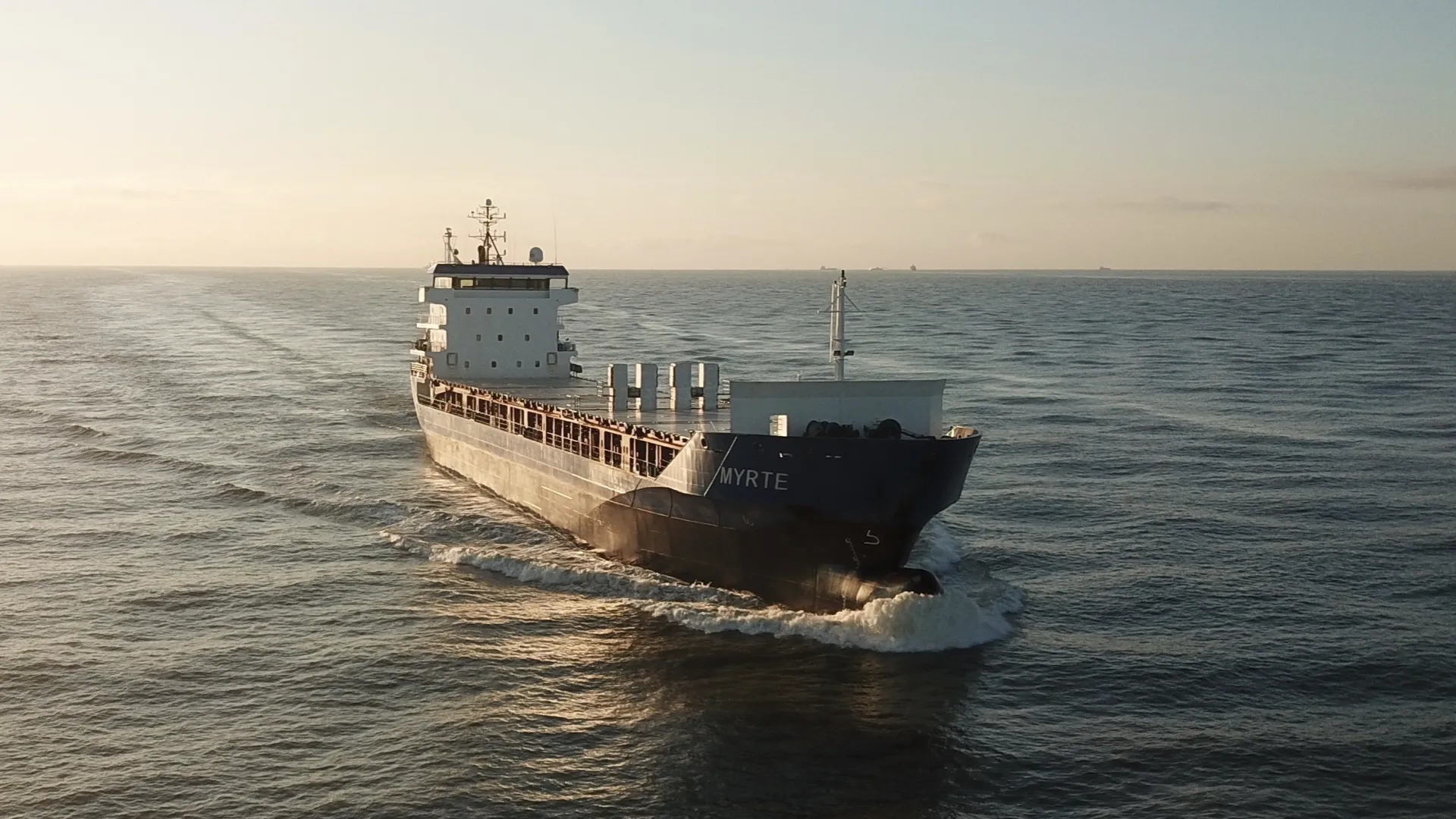
For the coastal ships Marit and Myrte, the opportunities offered by the existing propulsion configuration for improving energy efficiency were investigated. With an Express Analysis, various measures were investigated using CFD, and the expected returns were compared with the required investments.
For both ships, the analysis indicated a possible improvement in propulsion efficiency of more than 4%. A Pre-Swirl Stator was selected on the basis of the technical and economic assessment. The devices for both ships were then further designed, manufactured and installed.
Approach to ESD Projects
An ESD project begins with the question of what improvement is sought for the ship and when a possible modification can be carried out. Data on the hull, stern, propeller and rudder are linked to the usual speeds, draughts, loading conditions and power demand. The current condition and work already planned are also taken into account. In this way, a starting point emerges that reflects how the ship will actually be used after maintenance or modification.
An Express Analysis can be carried out as an initial technical investigation. CFD is used to investigate where losses occur and which measures are promising. The potential energy saving is linked to an initial estimate of the investment required and the technical integration. On that basis, the owner can determine whether further development of an ESD offers sufficient potential.
For promising solutions, a more extensive comparison of design variants follows. Shape, position and dimensions are matched to the interaction between the hull, propeller and rudder. The hydrodynamic design is then linked to the structural substantiation, available space, maintenance access and installation planning. The performance and economic calculations remain based on the same ship configuration and operating conditions.
Following a positive project decision, detailed engineering, production and preparation for installation can follow. The parties involved tailor the required assessments, installation checks and testing to the project. In retrofit projects, this is linked to the scheduled docking work; in newbuild projects, to the further development of the propulsion design.
When performance verification forms part of the assignment, the reference condition, measurement method and acceptance criteria are agreed in advance. In this way, the final assessment reflects the technical and economic assumptions on which the investment is based.
Having Your ESD Project Assessed
Would you like to know whether an ESD can reduce your ship’s fuel consumption, or which device suits a scheduled docking or newbuild project? We would be pleased to explore the possibilities for your propulsion configuration with you.
For an initial assessment, data on the hull, stern, propeller and rudder are needed, together with the operational profile and corresponding power demand. Information about the current condition, planned docking work and any other modifications helps establish the right starting point.
Please contact us to discuss your project and the potential energy saving. Even if not all the technical data are available yet, we can look together at what information is needed and whether an Express Analysis would be a suitable first step.
Pre-Swirl Stator on Two Coastal Ships
For the coastal ships Marit and Myrte, the opportunities offered by the existing propulsion configuration for improving energy efficiency were investigated. With an Express Analysis, various measures were investigated using CFD, and the expected returns were compared with the required investments.
For both ships, the analysis indicated a possible improvement in propulsion efficiency of more than 4%. A Pre-Swirl Stator was selected on the basis of the technical and economic assessment. The devices for both ships were then further designed, manufactured and installed.