Which Geometric Installation Space Limits the Positioning of a Propeller Nozzle in Relation to the Hull and Stern?
Author: Jeroen Berger • Publication date:
During a retrofit or a new design, the first technical question around the propeller zone typically concerns the available space. Once the application of a propeller nozzle is considered, it must first be established whether the existing or planned aftbody geometry permits the required clearances. Only after these physical boundaries have been defined does further evaluation of configurations become meaningful.
The practical question therefore becomes: within which geometric space can a nozzle actually be positioned relative to hull, propeller and rudder?
In practice, a nozzle is constrained not only by its profile shape, but primarily by the space already occupied by the propeller, shaft line and rudder. The position of the hull opening, the distance to the rudder and the location of the shaft line together determine how much freedom remains to position a nozzle around the propeller without placing other components of the propulsion system under constraint.
Space Around the Propeller Zone as the Starting Point of the Configuration
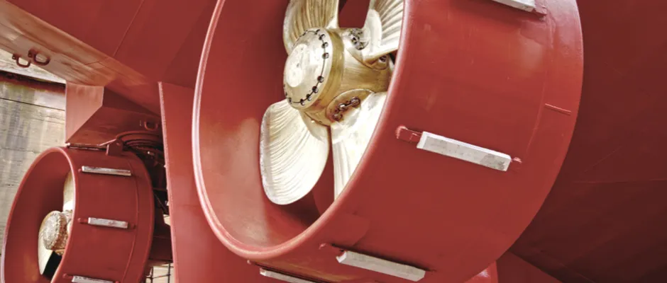
The first physical boundary lies in the aftbody opening itself. Around the propeller zone, sufficient radial space must be available to install a nozzle without the nozzle wall being positioned too close to the hull. This distance determines not only whether the nozzle can be installed structurally, but also whether the flow along hull and nozzle can develop without abrupt disturbance.
With a relatively tight opening around the propeller, this directly limits the outer diameter of the nozzle and the position in which it can be centred relative to the propeller. The available space therefore becomes a design framework within which the relationship between hull, nozzle and propeller must be defined.
The shape of the aftbody plays a direct role. Full-bodied hull forms may allow different radial clearances than more slender hull forms, where the propeller opening more closely follows the propeller diameter. The hull geometry therefore determines how much margin remains to position a nozzle such that both installation and flow development remain reproducible.
The Distance to the Rudder Determines System Development Downstream
Behind the nozzle lies a second geometric boundary. The distance between the propeller plane and the rudder blade determines how much length remains available before the outflow reaches the rudder.
When a nozzle is positioned relatively close to the rudder, not only does the structural position change, but so does the flow field approaching the rudder. In inland navigation and offshore retrofit projects, this distance often proves to be one of the primary geometric constraints. In such configurations, even small positional changes can quickly propagate into the behaviour of the propulsion system.
What becomes decisive here is not the absolute distance to the rudder, but the relationship between nozzle, propeller plane and rudder position once the available axial space becomes limited. The aftbody geometry then determines to what extent the flow field can develop between these components before the next element is encountered.
Precision Around the Shaft Line Determines the Actual Installability
Even when the principal dimensions around the propeller zone appear to provide sufficient space, the final positioning of a nozzle is governed by the precision around the shaft line. The centring of the nozzle and the tip clearance between the propeller blade and the inner surface of the nozzle form a direct geometric boundary.
A small deviation in centring can already change the available clearance around the blade tip. This affects not only the mechanical margin around the propeller, but also the distribution of velocity and pressure across the propeller plane. Evaluation of a configuration becomes meaningful only when the relationship between shaft line, propeller diameter and inner ring can be defined with sufficient accuracy.
The interpretation shifts when the same propeller opening is assessed from these precision requirements. An opening that appears sufficient based on global dimensions may still offer limited margin when accurate centring or restricted tip clearance is applied.
Vertical Position of the Propeller Zone as an Additional Boundary
In addition to radial and axial space, the vertical position of the propeller zone also plays a role. The underside of the aftbody and the shape of the opening determine how much vertical space remains available for a nozzle around the propeller.
When the shaft line is positioned relatively close to the hull, the space above or below the nozzle may become limiting for the final diameter or position. In such configurations, the aftbody geometry becomes decisive for symmetry around the propeller plane.
The aftbody geometry cannot always be fully assessed in a single projection. An arrangement that appears sufficient in side view may prove less tolerant in cross-section or in relation to the actual hull form.
Different Starting Points in Newbuild and Retrofit
In a new design, the position of nozzle, propeller and rudder can be developed in conjunction from the outset. The aftbody geometry is then partly defined by the intended propulsion configuration.
In existing vessels, the starting point is different. The position of shaft line, rudder and propeller opening is usually fixed. The possible application of a nozzle must therefore be evaluated within a geometry already determined by the original construction.
This distinction shapes the design process. In newbuild, the available space around the propulsion system can be configured. In retrofit, the first step is to determine which margins the existing configuration still permits before further design steps become meaningful. In retrofit projects, this geometric assessment often proves decisive before hydrodynamic variants are explored further.
Geometry as the First Selection Criterion
When a nozzle is considered, the technical evaluation often shifts early towards profile variants or hydrodynamic optimisation. Yet the primary feasibility question typically lies in the available space around the aftbody.
Once the radial space around the propeller, the axial distance to the rudder, the shaft line position and the vertical clearance within the propeller opening are defined in conjunction, a clear picture emerges of the physical boundaries within which the system must operate.
Within those boundaries, it becomes clear which configurations can be positioned before further hydrodynamic considerations become meaningful. In some projects, this geometric step already determines the direction of the subsequent configuration choice.
This Article Within the Series
Within Propeller Nozzle: Technology and Configuration, geometric installation space forms the first technical system layer of the propulsion concept. This article shows within which radial, axial and vertical limits a nozzle can be positioned relative to hull, propeller and rudder, and where the physical margins of the configuration begin and end.
The next step in the series shifts from geometry to system interaction. In How Does the Interaction Between a Propeller Nozzle, Propeller and Rudder Affect the Ship’s Propulsive Behaviour, it is explained how inflow, blade loading and rudder loading relate within the same installation configuration, and how this interaction affects power, vibration behaviour and manoeuvring characteristics.
For shipping companies, shipowners and technical managers seeking to translate these principles into a project-specific configuration, the page Propeller Nozzle for Ships provides a direct continuation. There, geometric installability, system interaction and operating profile are brought together in a traceable assessment for selecting a nozzle configuration in both newbuild and retrofit.