How Does the Interaction Between a Propeller Nozzle, Propeller and Rudder Affect the Vessel’s Propulsive Behaviour?
Author: Jeroen Berger • Publication date:
When deviations in fuel consumption, course stability or wear around the propeller zone become visible in practice, a single component rarely proves decisive. What manifests on board typically results from the combined functioning of the propeller nozzle, ship propeller and ship rudder within the existing aftbody configuration.
Within that configuration, it is determined how inflow reaches the propeller plane, how blade loading develops and how the rudder is engaged by the flow. The observable performance of the vessel, for example in power demand, vibration behaviour or steering response, therefore follows from the interaction of the complete system.
When this relationship remains out of view, an apparent primary cause can emerge. A corrective measure may appear locally justified, while loading shifts elsewhere in the system and introduces a new sensitivity.
For shipping companies and shipowners, an intervention on a single component only gains meaning once it is clear how the change propagates through the flow field and load distribution around the aftbody. The uncertainty rarely lies in the component itself, but in whether the overall configuration maintains a predictable load progression within the same operating profile.
The Nozzle as a Shaper of the Inflow
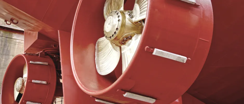
Between hull form and propeller, the nozzle determines how water reaches the propeller plane. It governs the distribution of velocity and pressure around the propeller circumference before the propeller converts the inflow into thrust.
As a result, not only the average blade loading is affected, but more importantly the uniformity with which that loading develops.
A more homogeneous inflow pattern allows the propeller to operate more steadily and keeps power demand stable under moderate variations in speed or resistance. When the inflow is more strongly directed or locally accelerated, this may be beneficial within a specific operating range while increasing sensitivity outside that range.
The significance of the nozzle therefore lies less in a single optimal operating point than in the extent to which the system absorbs variation without abrupt shifts in loading.
Propeller Behaviour Under Shifting Load Conditions
The propeller converts the incoming flow field into thrust and responds directly to changes in blade loading. A configuration tuned closely to a single design load may react noticeably differently once inflow or resistance changes.
The question is therefore not only whether the propeller performs efficiently under nominal conditions, but whether the overall propulsion system remains controllable outside that point.
In combination with an inflow-shaping nozzle, a configuration may remain stable within a limited bandwidth while operational flexibility decreases under varying conditions. This becomes visible during frequent manoeuvres, varying loading conditions or changes in water depth.
Small shifts in blade loading can translate into measurable variations in shaft power or a more pronounced vibration pattern.
Outflow Characteristics and Rudder Loading
Behind the propeller plane, an outflow pattern develops that reaches the rudder directly. This pattern results from the complete upstream flow chain.
The nozzle determines the degree to which the propeller slipstream is concentrated or dispersed and the angle at which the rudder blade encounters the flow. Steering forces and rudder loading follow from this actual inflow field.
A concentrated slipstream can support strong rudder response at low speed, which may be advantageous in working vessels or manoeuvre-intensive operations. At the same time, a strongly concentrated outflow can intensify local load peaks, making the system more sensitive to small rudder movements.
With a more dispersed outflow pattern, rudder loading develops more evenly and course behaviour is generally more stable.
The observed steering response is therefore not an isolated phenomenon, but the result of the interaction between hull inflow, nozzle and propeller as it manifests in the outflow field.
Geometry as a Fixed System Boundary
The relative distance between nozzle, propeller and rudder determines how much space the flow field has to develop. Tip clearance, rudder distance and the shape of the aftbody also influence how inflow and outflow stabilise before the next component is reached.
In newbuild projects, this relationship can be developed as an integrated design. In existing vessels, the installation configuration is largely fixed and the interaction is constrained by structural limitations.
Small deviations in centring, rudder distance or tip clearance can already produce noticeable shifts in load distribution or steering response without any visible defect.
Within retrofit projects, geometry does not act as a background condition, but as a fixed system boundary within which the propulsion system must continue to function.
Assessment of Propulsion as an Integrated Whole
The propulsive behaviour of a vessel results from the interaction between inflow quality, blade loading and rudder interaction within the same installation configuration and the dominant operating profile.
Optimising one component redistributes loading within the same system. What produces gains under one condition may increase sensitivity under another.
What becomes decisive is not a favourable result at a single operating point, but the extent to which the load pattern remains predictable under variation in speed, loading or manoeuvring.
A project-specific comparison of inflow, blade loading and rudder loading under identical assumptions shows whether the system distributes loads gradually or whether small changes lead to noticeable shifts in power demand or steering response.
The propulsive behaviour of a nozzle configuration gains meaning through the interaction between geometric installation space, the interplay of nozzle, propeller and rudder, and the operating profile in which the vessel operates.
This Article Within the Series
Within Propeller Nozzle: Technology and Configuration, the interaction between nozzle, propeller and rudder forms the second technical system layer after geometric installation space.
Where the preceding article Which Geometric Installation Space Limits the Positioning of a Propeller Nozzle in Relation to the Hull and Stern defines the radial, axial and vertical limits within which a configuration can function, the analysis here shifts to the hydrodynamic interaction between the components of the propulsion system.
The next step in the series moves the assessment framework further. In How Does a Modified Operating Profile Affect the Technical Basis of a Propeller Nozzle, it becomes clear how changes in speed, loading and operating conditions shift the load progression within the same configuration.
For shipping companies, shipowners and technical managers seeking to translate these principles into a project-specific decision, the page Propeller Nozzle for Ships provides a logical continuation. There, geometry, system interaction and operating profile converge in a traceable configuration for both newbuild and retrofit.