When Are 3D Measurement and Additional Dimensional Verification Necessary for Propeller Nozzle Replacement Without Available Drawings?
Author: Jeroen Berger • Publication date:
A propeller nozzle is designed on the basis of precisely defined dimensions, but it must fit into an existing structure whose actual installation geometry may shift over time. It is precisely in replacement without reliable drawings that the difference arises between design intent and the existing installation condition. What is symmetrical on paper may, in steel, have become slightly eccentric due to loading, repairs or local deformation.
Once geometric uncertainty becomes greater than the available design margin, verification shifts from an option to a necessity. The question then changes from design to execution: can the nozzle still be positioned and aligned demonstrably correctly on the basis of the available dimensions?
For shipping companies and shipowners, the core issue therefore lies not in the technical attractiveness of 3D measurement, but in whether missing or uncertain dimensions create an unacceptable risk for fit-up, centring and alignment within the operating profile.
If the Existing Situation Cannot Be Demonstrated to Correspond to the Drawing
3D measurement becomes necessary as soon as original construction drawings are missing, incomplete or no longer representative of the current installation condition. This occurs particularly in older vessels or in craft with multiple damage-repair and modification cycles.
A general lines plan says little about the actual hull form of the aft ship. Plate replacement or structural reinforcement may have altered the geometry locally. Once the possible deviation becomes greater than the clearance the new nozzle requires in order to continue functioning within design margins, relying on nominal dimensions is no longer defensible.
In that situation, geometric verification becomes a necessary step before design and fabrication begin.
If Fit-Up and Centring Must Remain Within Narrow Tolerances
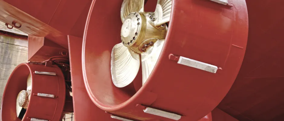
The position of the nozzle relative to the propeller shaft line and the rudder determines tip clearance, radial clearance and the flow pattern around the propeller.
In many configurations, the design tip clearance amounts to only a few millimetres. A deviation of a similar order may already lead to asymmetric loading, increased cavitation sensitivity or mechanical contact.
When these clearances must remain within limited tolerances in order to avoid hydrodynamic or mechanical problems, additional dimensional verification becomes necessary. A slight deviation in the shaft line or an opening in the aft ship that is not fully circular may otherwise already lead to eccentric installation.
In such situations, a 3D scan is not an optimisation, but a precondition for controlled execution.
If Earlier Damage or Deformation May Still Have an Effect
After grounding, collision or heavy loading, the aft ship may have been locally deformed, even when this has been repaired structurally. Plate replacement restores strength, but not automatically the original geometry.
When the nozzle is replaced, it must therefore be established whether the shaft line, hull form and connection details still remain within acceptable tolerances. The risk lies not in the visible repair, but in the difference between structural correctness and hydrodynamic alignment.
In that case, additional dimensional verification is the only way to place design and realisation once again on the same geometric basis.
If the Replacement Is Not Like-for-Like
As soon as profile, diameter or positioning differ from the original execution, the error margin for assumptions about available space and interaction with hull and rudder becomes smaller.
A larger diameter or modified profile shape makes small deviations in hull geometry directly relevant to clearance and alignment. In such cases, the existing situation must first be established exactly so that design and fabrication correspond to the actual boundary conditions.
Otherwise, the analysis may be based on a geometry that does not in fact exist.
If Tolerances Form Part of Formal Assessment
When the replacement forms part of a process assessed by a classification society, verifiable dimensions may form part of the technical file.
3D measurement then provides not only design input, but also objective documentation of the starting situation. Fit-up, centring and clearances then become traceable to measurements rather than assumptions.
For formal assessment, what matters above all is the reproducibility of the starting situation.
Where the Boundary Actually Lies
What is decisive in the end is the relationship between geometric uncertainty and the available design margin.
Where clearances are generous and the replacement is strictly like-for-like, conventional dimensional checks may be sufficient. As soon as tip clearance, centring and interaction with propeller and rudder become critical for the intended operating profile, it becomes rational to reduce geometric uncertainty in advance rather than having to correct it during installation or sea trials.
3D measurement and additional dimensional verification therefore become necessary when the actual installation geometry of the aft ship, shaft line and rudder arrangement cannot be established with sufficient certainty and the available design margin is smaller than that uncertainty.
Conclusion
3D measurement becomes necessary in nozzle replacement as soon as the actual installation geometry of the aft ship, shaft line and rudder arrangement cannot be demonstrated to correspond to the design basis and the available design margin is smaller than that geometric uncertainty. In that situation, additional dimensional verification is not an optimisation, but the condition for keeping fit-up, centring and alignment controllable within the same vessel context.
This Article Within the Series
Within Propeller Nozzle: Service Life, Retrofit and Regulations, the focus shifts from design and performance validation to the operational phase of the propulsion system.
Where the preceding cluster, Propeller Nozzle: Design and Performance Validation, described how nozzle variants are compared and substantiated methodically, the focus here is on how existing configurations are assessed when geometry, loading and wear develop over time.
This first article addresses the situation in which a nozzle must be replaced while reliable drawings are missing or no longer representative of the current installation condition. In such cases, the technical question shifts from design to geometric verification.
The next step in this cluster addresses another practical assessment. In When Can an Existing Propeller Nozzle Be Retained Following a Change in Propeller Loading it is elaborated under which conditions an existing nozzle can continue to function in a technically responsible way when propeller loading or propulsion configuration changes.
For shipping companies, shipowners and technically responsible parties who want to translate these maintenance and retrofit decisions into a concrete project assessment, the page Propeller Nozzle for Ships forms a logical continuation. There, geometric verification, load analysis and configuration choice come together in a traceable nozzle arrangement for newbuild and retrofit.