What Types of Ship Propellers Are There and What Are Their Characteristics?
Author: Jeroen Berger • Publication date:
The ship propeller is the central element of a vessel’s propulsion system and has a major impact on energy efficiency, maneuverability and operational reliability on board. The selected propeller configuration determines how effectively the available engine power is converted into thrust, and it directly affects fuel consumption, emissions and the loading of the propulsion train. For shipping companies and shipowners, the choice of the right propeller type is therefore not a minor decision, but a strategic consideration with structural impact on operating costs and performance over the vessel’s lifetime.
At the same time, vessel types, areas of operation and operational profiles vary widely, so a single universal solution does not exist. To meet those diverse operational requirements, several propeller types have been developed in practice, each with specific hydrodynamic and operational properties. This article explains the main variants, placing their characteristics in the context of fuel efficiency, emissions reduction and compliance with relevant international standards and guidelines.
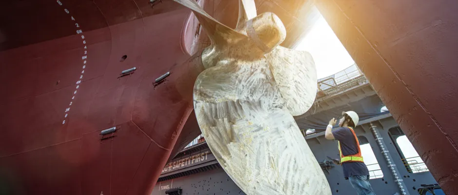
Fixed Pitch Propeller (FPP)
The Fixed Pitch Propeller (FPP) is globally the most widely applied configuration of conventional ship propulsion. In this type, the blade pitch is permanently fixed and cannot be adjusted during operation. That fixed geometry results in a simple and mechanically robust construction, characterized by high reliability and relatively low maintenance needs. In operational profiles with a constant speed and a steady load, such as bulk carriers, container ships, oil tankers, inland vessels with predictable routes and fishing vessels, this character aligns well with operational practice. Under such conditions, an FPP can operate efficiently and delivers stable and predictable propulsion performance.
Opposite these advantages is the fact that the fixed pitch limits flexibility when the vessel regularly operates at varying speeds or under changing conditions. Because the propeller geometry cannot be adapted to changing load or operating state, efficiency can decrease in such situations. The use of an FPP therefore requires careful alignment between propeller design, engine configuration and the intended operational profile, so the simplicity and efficiency of the system come into their own within the intended operational limits.
Controllable Pitch Propeller (CPP)
In contrast to a fixed propeller, the Controllable Pitch Propeller (CPP) allows the blade pitch to be varied while underway. This enables propulsion to be matched more precisely to loading, speed and maneuvering needs, without engine speed always having to play the same role as with a fixed propeller. This makes a CPP particularly relevant for vessels operating under varying conditions, such as tugboats, offshore support vessels, cruise ships and ferries, where low-speed control and frequent power transients carry significant weight in practice.
That controllability delivers operational benefits and can, depending on schedule and load profile, amount in practice to approximately 5 to 10 percent fuel savings. At the same time, better alignment between engine load and propeller load can contribute to lower emissions and a steadier operation across the profile. This allows the CPP to support compliance with frameworks such as the Energy Efficiency Existing Ship Index (EEXI), the Carbon Intensity Indicator (CII), the European Union Emissions Trading System (EU ETS) and FuelEU Maritime, which from 2025 progressively tightens the greenhouse gas intensity of onboard energy on a well-to-wake basis, for example for fuels and energy carriers such as bio-LNG, LNG, (bio- and e-)methanol, hydrogen, ammonia and other renewable or low-carbon options.
Against this background, attention to flexibility in the propulsion train is increasing, especially now that CII ratings weigh more heavily in operational choices. For that reason, shipping companies and shipowners more often consider a CPP, particularly when the operational profile requires variable loading and precise thrust control. This keeps flexibility and efficiency better in balance and creates scope to optimize performance and compliance in an integrated way.
Ducted Propellers
For vessels where thrust weighs more heavily than controllability, a ducted propeller is often a suitable choice. In this concept, a propeller nozzle surrounds the propeller and guides the water flow along the blades. That guidance can increase thrust at low speed, providing higher thrust in the operating range where such vessels most often operate. For that reason, the ducted propeller is widely used on tugboats, dredgers, supply vessels and inland vessels that maneuver frequently, particularly in shallow water.
How large this effect is in practice depends strongly on the geometry of both the nozzle and the propeller and on the interaction with the hull. Nozzle design, blade count and pitch distribution interact with the hull wake, the hull-induced inflow to the propeller. Together, these factors determine tip losses and other energy losses, and thus the final efficiency. When measurements and calculations in this speed range are carefully set up and consistently documented, that interaction can lead to demonstrable efficiency gains and more predictable performance.
To compare performance objectively and substantiate design choices, the assessment can be built on towing-tank and cavitation-tunnel testing in accordance with ITTC guidelines, possibly supplemented with open-water tests. The outcomes can then be verified during sea trials, with sea-trial measurements corrected in accordance with ISO 15016 and with operational monitoring in accordance with ISO 19030. This creates a traceable basis for comparison and decision-making, provided measurement conditions, assumptions and applied corrections are recorded transparently.
Opposite the advantages at low speed is the fact that at higher speeds the nozzle resistance increases and total efficiency decreases. The application therefore fits primarily when maximum thrust, stability and low-speed control weigh more heavily than a high cruising speed. Particularly in power-oriented operational profiles, the ducted propeller thus performs best.
Azimuth Thrusters and Podded Propulsion Units (Pods)
For vessels requiring high maneuvering performance, such as cruise ships, ferries and specialized offshore vessels, azimuth thrusters and podded propulsion units are widely used. An azimuth thruster can rotate 360 degrees around the vertical axis, allowing the thrust direction to be oriented in any desired direction. This enables maneuvers such as side-stepping and dynamic positioning to be performed efficiently and accurately, especially when a rapid response to changing environmental conditions is required. Because thrust and steering function are integrated in one unit, low-speed control increases and response time shortens, which delivers a direct advantage in confined or busy waterways.
From the same need for integration and controllability, a podded propulsion unit is often a logical next step. In this concept, the electric motor is housed inside the pod and drives the propeller directly, which allows a conventional mechanical transmission line to be largely eliminated. This configuration combines efficient propulsion with very precise maneuverability and is often associated in practice with lower noise and vibration levels. For passenger ships, this reduces onboard noise and vibration levels, improving passenger comfort, while the quieter drive can also help limit underwater noise in line with guidelines such as ICES 209, and where relevant with national regulations.
In modern vessel designs, pods are therefore frequently integrated in hybrid or fully electric propulsion systems. Within such an energy architecture, they can contribute to decarbonization, while simultaneously fitting within applicable operational requirements and environmental standards. Which solution fits best depends in practice on the operational profile, the selected energy architecture and the desired degree of maneuverability, because that interplay determines where the greatest operational and technical added value arises.
Waterjets
A waterjet draws in water through an inlet under the hull and expels it at high speed through a nozzle. Because the jet is generated inside the hull and no propeller or rudder blade protrudes below the hull, the effective draft generally remains limited and the risk of damage due to ground contact decreases. At the same time, the system responds quickly to power changes, which provides a functional advantage particularly in dynamic operation. At high Froude numbers, where vessel speed is related to ship length and gravity, the cavitation margin is often favorable, which explains the typical application range of waterjets.
From this combination of properties, waterjets are especially suitable for high-speed ferries, patrol vessels and yachts with high acceleration and frequent stop-start cycles. At higher speeds, hydrodynamic efficiency can be competitive with that of conventional propulsion systems. However, during prolonged operation at lower cruising speeds, this picture changes, because a classic propeller system usually achieves a higher overall efficiency under such conditions.
In addition to hydrodynamic performance, maintenance requires specific attention. For waterjets, the focus lies on the internal jet-unit components, including the impeller, the rotating bladed wheel that accelerates the flow, and the stator, whose fixed guide vanes reduce residual swirl in the jet. In addition, seals, bearings and inlet protection are decisive for reliability. A steady and undisturbed inflow to the inlet, limiting additional resistance due to fouling and adequate protection against floating debris are essential for stable performance.
The maneuvering and steering functions also differ from those of a conventional propeller-rudder configuration. Reverse thrust and fine steering are typically achieved with a reversing bucket that redirects the water jet, or with steering devices with adjustable vanes in the outlet. As a result, operation differs fundamentally from classic systems, which in practice often requires specific crew training to ensure safe and reproducible maneuvers.
For performance verification, the process usually starts with model tests and numerical flow analyses of the inlet, jet unit and outlet configuration. The results can then be verified during sea trials, with sea-trial measurements corrected in accordance with ISO 15016 and supplemented with operational monitoring in accordance with ISO 19030. Provided measurement conditions, assumptions and applied corrections are recorded transparently, this yields a traceable and technically verifiable basis for sizing, selection and certification.
Cycloidal Propulsion
A cycloidal thruster, also known as the Voith Schneider Propeller (VSP), uses a rotor with a vertical axis on which several blades with adjustable pitch are mounted. By varying the blade pitch cyclically during rotation, the thrust vector, both in direction and magnitude, is continuously controlled without the use of a separate rudder. This creates a direct link between steering and power commands and the generated thrust. On board, this is experienced as a very predictable and rapid response, including side-stepping and turning on the spot.
That direct and continuous thrust-vector control makes this propulsion type particularly suitable for vessels that operate in confined spaces and berth frequently. Examples include port tugs, ferries with short routes, construction and offshore support vessels and research or patrol vessels that regularly require station-keeping. VSPs can deliver high thrust in any direction and generally reduce the time needed to correct course or position. During longer transits at higher speed, however, hydrodynamic efficiency is usually lower than with a conventional fixed or controllable pitch propeller configuration, with or without a nozzle. The added value of cycloidal propulsion therefore lies primarily in short, maneuver-intensive operating profiles.
These operational advantages impose specific requirements on installation and integration. The supporting structure around the rotor must safely absorb cyclic loads and peak moments, while simultaneously ensuring a calm and uniform inflow to the rotor. In maintenance, the emphasis is on blade root bearings, seals, the pitch mechanism and the hydraulic control system. Additional protection against floating debris and a tightly structured lubrication and inspection regime are important to limit unplanned downtime. On the drive side, both diesel-mechanical and diesel-electric configurations are common, with integration with dynamic positioning and an appropriate emergency-stop logic requiring extra attention in design and operation. In practice, this often goes hand in hand with targeted crew training.
To substantiate performance and behavior, model tests are regularly used for the performance assessment, particularly to gain insight into maneuverability, response and interaction with the hull. Open-water investigations with varying blade pitch can provide reference values for the rotor. Numerical flow analyses, including CFD calculations, supplement this by explicitly accounting for cyclic blade pitch and rotating inflow. In concert, these steps provide a technically substantiated basis for design, sizing and further verification.
Contra-Rotating Propellers and CPP in a Nozzle
Contra-rotating propellers use two rotors on the same shaft that rotate in opposite directions. The aft rotor can recover part of the residual rotation in the slipstream, the outflow behind the forward propeller, reducing swirl losses. As a result, for a given diameter, a higher disk loading can be achieved and the cavitation margin is favorable in many cases, depending on design and operating point. Balancing this, the shaft line, bearings and seals become mechanically more complex, so alignment, torsional vibrations and maintenance are more critical and usually require explicit attention in design and verification.
Precisely when propeller diameter is constrained by draft or stern geometry, or when a large amount of power must be transmitted through one shaft line, this arrangement can be of interest. In such boundary conditions, the ability to extract more thrust from a limited diameter is often decisive. Applications range from single-shaft vessels with high power density to azimuth thrusters with contra-rotating sets, where course-keeping and response weigh heavily and integration in the unit is decisive for performance.
Where contra-rotation primarily targets slipstream efficiency and disk loading within a limited diameter, a CPP in a nozzle targets a different combination of properties. A controllable pitch propeller, CPP, in a nozzle combines thrust at low speed with controllability over a wide load range. The nozzle can increase disk loading and thus the bollard pull, the static thrust, while the controllable pitch allows fine dosing of thrust during load changes and maneuvers. This aligns with profiles with highly dynamic loading, such as towage services, supply and dredging operations, where low-speed control and rapid response weigh heavily in practice. As with nozzle configurations in general, the resistance of the duct increases at higher speeds, so efficiency can decrease as the operating point shifts toward cruising speed.
In both cases, the final gain is strongly determined by detailed design and inflow conditions. Blade count and pitch distribution must fit the hull wake, because that interaction helps determine the load distribution over the blade and the efficiency. Skew, the blade’s skew angle, and tip rake, the backward offset of the blade tip, influence cavitation behavior and vibration level, while the hub ratio, the ratio between hub and outer diameter, affects both strength and inflow. Material selection and any ice-class requirement also limit the allowable loading profile and help define acceptable safety margins. On the drive side, a careful torsional-vibration analysis, a sound lubrication and sealing concept and a clear pitch and rpm strategy are important, so that performance and reliability remain demonstrably in balance.
When propeller diameter is limited and higher disk loading or additional slipstream efficiency is desired, a contra-rotating propeller can be suitable. If maximum low-speed thrust with precise control is central, a CPP in a nozzle is more obvious. For longer routes at higher cruising speed, a conventional FPP or CPP generally remains the most efficient, because these configurations usually score more favorably on resistance and overall efficiency in that speed range.
Strategic Consideration for Shipping Companies and Shipowners
The choice of propeller type is a strategic consideration, because it directly affects energy efficiency, emissions and operational reliability across the actual operational profile. For that reason, it is sensible to base selection on an integrated assessment in which technical properties, operational deployment and applicable regulation demonstrably align.
In practice, this starts with an analysis of operational behavior and the relevant load points, followed by calculating promising configurations with traceable and validated methods. Model testing in accordance with ITTC guidelines can be combined with sea trials, with sea-trial measurements corrected in accordance with ISO 15016, and with operational monitoring in accordance with ISO 19030. This creates a technically verifiable basis to compare performance, risks and maintenance impact and to substantiate the fit with frameworks such as EEXI, CII, EU ETS and FuelEU Maritime.
The final choice is preferably placed within a life-cycle cost analysis (LCCA), in which fuel consumption, maintenance strategy and policy costs are assessed in conjunction. On balance, the most responsible option is usually the configuration that, given the intended operational profile, offers the best balance under controlled conditions between demonstrable CO2 reduction, manageable technical risks and a predictable approval trajectory with the classification society.
About This Article
This article forms part of the background information on the propeller as a product and falls within the cluster Ship Propeller Types and Propulsion Configurations. Its core premise is that no single propeller type is universally optimal, but that performance, efficiency and operational reliability arise from the interaction between propeller configuration, operational profile and operational requirements. For a project-specific elaboration, the page Custom Ship Propeller logically builds on this context.
For a deeper dive into the design choices underlying these configurations, What Are Important Design Principles for an Efficient Ship Propeller connects directly. This article describes how blade geometry, inflow and load distribution determine efficiency, cavitation behavior and vibrations, regardless of the chosen propeller type.
The practical translation from propeller type to application is further elaborated in How Does Ship Propeller Selection Differ by Ship Type, which explains why the same configuration performs well in one segment and presents limitations in another.
When the choice of a propeller type is placed in a broader context of efficiency and regulation, How Does a More Efficient Ship Propeller Contribute to MARPOL Annex VI, EEXI/CII, and NOx Reduction provides additional depth. This article shows how configuration choices can conditionally affect fuel consumption, emissions and the substantiation toward compliance frameworks.
Together, these articles position the propeller not as a separate component, but as an integral part of a coherent design and decision-making chain within contemporary shipping.