
- English
- Nederlands

Pre-Duct
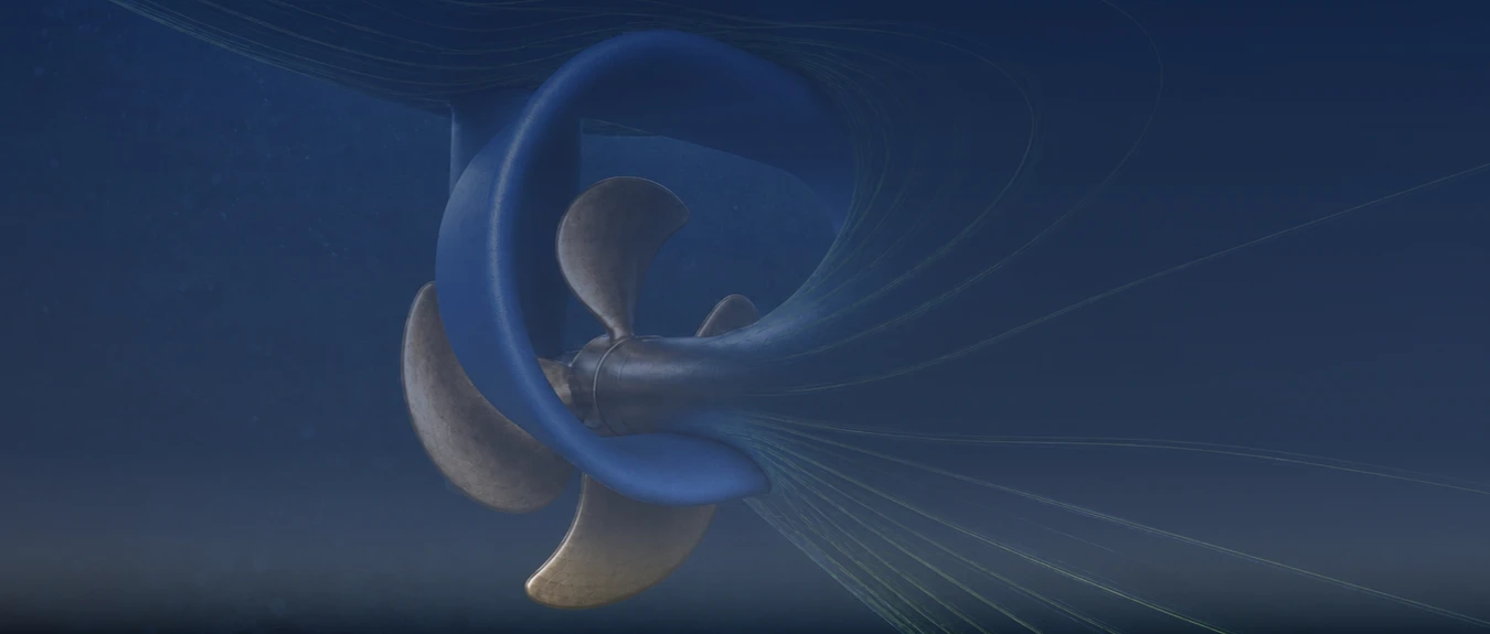
A Pre-Duct is an Energy Saving Device (ESD) with a profiled duct at the stern, ahead of the ship propeller. The duct influences the wake field behind the hull: the distribution of water velocity and flow direction in the inflow to the propeller. Suitable geometry can reduce the required propeller power at the same ship speed and thereby lower fuel consumption and the associated CO2 emissions. In suitable applications, a fuel saving of approximately 3–5% is a realistic indication; the actual benefit is determined by factors including stern shape, wake field, propeller configuration, operating conditions and operational profile. To this end, the changed inflow and the forces on the hull, duct and propeller are assessed together. The shape and position are matched to the stern, propeller configuration and actual operational profile. In cooperation with a specialist international partner, we support shipping companies, technical managers and shipyards in selecting a Pre-Duct and coordinating the project, from the initial feasibility assessment and hydrodynamic analysis through design and engineering, production and delivery to preparation for implementation on board.
Available worldwide
How Duct and Propeller Operation Influence Each Other
The profiled shape of the duct can accelerate parts of the inflow and redistribute the water across the propeller plane. The local inflow to the propeller blades and the pressure distribution around the stern change as a result. A well-matched duct can thus contribute to more favourable interaction between hull and propeller.
Pressure and friction forces also act on the duct itself. The pressure distribution may produce a forward force, while the additional wetted surface and any flow separation cause resistance. The rotating propeller in turn influences velocity and pressure around the duct. The analysis maps this interaction and shows the combined outcome of the different contributions under the operating conditions investigated.
Matching Duct Shape and Position to the Wake Field
The shape of the hull and stern and the existing appendages cause differences in inflow across the propeller plane. For a Pre-Duct, the questions of which parts of this flow can be modified and how the propeller uses the changed inflow are investigated. The design choice connects that flow modification with the forces on the duct and their combined influence on required power.
The dimensions of the duct opening, profile cross-section, length, setting angle and position determine how the water is guided. The distance from the hull and propeller and the shape of any supports also influence the local flow. These geometric choices are developed together so that the duct suits the wake field and can be fitted within the available space.
If the existing propeller is retained, the duct is matched to it. If a different propeller is also being considered, both changes are investigated together. Speed, draught, trim and propeller loading determine the operating conditions that the design must cover. Laden and ballast operation are assessed for their respective inflow conditions and expected effect on power.
When Does a Pre-Duct Offer Sufficient Hydrodynamic Potential?
A Pre-Duct may be particularly attractive if the existing inflow to the propeller offers sufficient scope for targeted improvement of the axial velocity distribution. This may be the case, for example, where parts of the propeller plane are supplied with relatively slow or uneven inflow because of the stern and a duct can guide this flow more favourably towards the propeller.
Practical suitability also depends on the space available for the duct, the distance from the propeller and the possibilities for integrating the supports suitably from both a hydrodynamic and structural perspective. Propeller loading and the operating points at which the ship spends most hours also determine how much value modified inflow can offer.
Ship type alone therefore says little about suitability. Two comparable cargo ships may have different potential for improvement because of differences in stern shape, wake field, propeller and operational profile. The relevant question is which flow losses are present in the existing configuration and whether the duct can specifically address them without additional resistance reducing the benefit too much.
An initial hydrodynamic assessment therefore brings together the existing wake field, propeller operation and available installation space. It can thus be established early whether further development of a Pre-Duct offers sufficient potential or whether another propulsion measure better addresses the losses identified.
A Pre-Duct or Stator Fins Ahead of the Propeller
A Pre-Swirl Stator (PSS) uses fixed fins to impart a directed rotational component to the inflow. In a Pre-Duct, the effect of duct geometry on the flow and forces around the stern is central. Both mechanisms can come together in one design. A duct may contain fins that generate pre-swirl, while a PSS can also influence the axial velocity distribution. The comparison therefore focuses on the specific designs and their influence on required propeller power.
A Propeller Boss Cap Fins (PBCF) device and a Rudder Bulb operate further downstream, around the propeller hub and rudder. A Pre-Duct changes the flow reaching these components. For a combination, the combined effect on power is established, with attention to the interaction and changed loading of the propeller and rudder.
The condition of the existing plant is the starting point. If fouling is severe, the propeller is damaged or it is less well matched to the operational profile, the necessary maintenance or modification is established first. That choice provides the basis for assessing the additional value of a Pre-Duct.
Establishing the Power Benefit of the Complete Configuration
Computational Fluid Dynamics (CFD) can be used to develop and compare duct geometries. The forces on the hull, duct and supports are assessed together with propeller thrust, torque and rotational speed. The influence on the rudder is included where it matters to the outcome. The local flow change is thus linked to the power difference for the complete propulsion configuration.
For the comparison, the self-propulsion point is established, internationally referred to as self-propulsion. The propulsive and opposing forces are then in equilibrium at the ship speed being investigated. The designs with and without a Pre-Duct are compared at the same speed and corresponding draught, trim and ship condition. The required rotational speed may differ. Torque and rotational speed together determine how much power is delivered to the propeller.
The way in which the propeller is represented in the calculation must adequately capture its influence on flow and pressure around the duct. A simplified propeller model may be useful for an initial comparison of design variants. For the final performance expectation, the additional checks or refinement needed are assessed. The analysis covers the relevant speeds and loading conditions, so that it also becomes apparent where the benefit diminishes or the duct requires additional propulsion power.
Cavitation, Flow Separation and Fluctuating Loads
The changed inflow alters the loading that the propeller blades experience during each revolution. Alongside average power, relevant changes in cavitation, pressure pulses and vibration excitation are therefore investigated. Around the duct itself, the flow along the profile is assessed, as are the locations where flow separation, low pressures or cavitation may occur.
Speed, propeller loading and immersion determine which situations require attention. Different inflow may change the loading on the duct and propeller, even if the design performs favourably at the original design condition. The design choice therefore combines the expected power benefit with acceptable flow behaviour and suitable loads. The necessary calculations and tests are tailored to those considerations.
Scale Effects and Verification on the Actual Ship
At model scale, the boundary layer along the hull and the local inflow at the duct differ from those at full scale. The ratio of pressure to friction forces also changes. Because the duct operates in this very flow, these scale differences are taken into account when translating model results into the expected power benefit on the ship.
Full-scale CFD can support this assessment. The outcome depends on factors including the turbulence model, computational mesh resolution, propeller modelling and assumed surface roughness. Comparison with suitable model tests or other measurement data helps to assess the calculations. The uncertainty is compared with the magnitude of the predicted power difference. The substantiation needed to support the design or investment decision thus becomes apparent.
After installation, the achieved effect can be assessed using sea-trial or operational data. Measurements of speed, power and rotational speed are linked to loading, draught, trim and relevant weather and sailing conditions. For a retrofit, work undertaken during the same docking is also recorded. A new hull coating, hull cleaning or propeller maintenance may also lower the required power. The reference and measurement setup are adjusted accordingly so that the Pre-Duct contribution can be assessed separately as far as possible. Calculated expectations and measured results remain linked to their own conditions and assessment method.
Structural Integration and Maintenance Around the Stern
The duct and its attachments transfer the hydrodynamic forces and moments to the stern. The shell structure and any internal reinforcements must be able to carry these loads. Shape, position and attachment are therefore developed together. A modification for structural integration is also assessed for its influence on flow behaviour.
Where necessary, stresses and deformations are investigated using the method known internationally as the Finite Element Method (FEM). Suitable load cases are used for the duct, supports and hull connections. Fluctuating loads, fatigue and possible vibration problems are taken into account where they are relevant to the chosen design.
For a retrofit, the existing stern structure, propeller position and other appendages determine what integration is feasible. Clearance from the propeller, access for installation and provision for later inspection, cleaning and maintenance form part of the design choice. The required reinforcements and installation sequence are matched to the available docking period. For a newbuild, the stern, duct, propeller and rudder can be designed together at an earlier stage. In both cases, the technical documentation is tailored to the ship-specific assessment and applicable classification requirements.
During operation, the duct surface, attachments and surrounding structure are checked for fouling, damage and deformation. The findings determine which maintenance or further assessment is needed. If the propeller, rudder or operational profile is subsequently changed, the duct’s suitability for the changed flow and the continued applicability of previous performance expectations are investigated again.
From Power Difference to Annual Fuel Savings
For the annual forecast, the power difference in each relevant sailing condition is linked to the corresponding operating hours. Both favourable and less favourable operating points contribute. A duct that offers a benefit mainly around the original design speed therefore makes a different annual contribution if the ship usually sails considerably more slowly. The calculation shows how much of the design benefit can be used in actual service.
To translate this into fuel consumption, losses in the drivetrain and the engine’s specific fuel consumption at the changed load are taken into account. The difference in propeller power is thus linked to the consumption of the propulsion plant. The expected CO2 reduction follows from the calculated difference in fuel consumption and the type of fuel used.
For a retrofit, the additional costs of the Pre-Duct, stern modifications and installation are distinguished from maintenance that is planned even without the project. Design, engineering, production and any additional docking time form part of the investment. The expected saving is assessed over the ship’s remaining period of operation, with attention to changes in the operational profile and maintenance condition. The conditions under which the chosen design offers sufficient technical and economic value thus become apparent.
Pre-Duct
In cooperation with a specialist international partner, we support shipping companies, technical managers and shipyards in selecting a Pre-Duct and coordinating the project, from the initial feasibility assessment and hydrodynamic analysis through design and engineering, production and delivery to preparation for implementation on board.
Available worldwide
What Is a Pre-Duct?
A Pre-Duct is an Energy Saving Device (ESD) with a profiled duct at the stern, ahead of the ship propeller. The duct influences the wake field behind the hull: the distribution of water velocity and flow direction in the inflow to the propeller.
Suitable geometry can reduce the required propeller power at the same ship speed and thereby lower fuel consumption and the associated CO2 emissions.
In suitable applications, a fuel saving of approximately 3–5% is a realistic indication; the actual benefit is determined by factors including stern shape, wake field, propeller configuration, operating conditions and operational profile. To this end, the changed inflow and the forces on the hull, duct and propeller are assessed together.
The shape and position are matched to the stern, propeller configuration and actual operational profile.
How Duct and Propeller Operation Influence Each Other
The profiled shape of the duct can accelerate parts of the inflow and redistribute the water across the propeller plane. The local inflow to the propeller blades and the pressure distribution around the stern change as a result. A well-matched duct can thus contribute to more favourable interaction between hull and propeller.
Pressure and friction forces also act on the duct itself. The pressure distribution may produce a forward force, while the additional wetted surface and any flow separation cause resistance. The rotating propeller in turn influences velocity and pressure around the duct. The analysis maps this interaction and shows the combined outcome of the different contributions under the operating conditions investigated.
Matching Duct Shape and Position to the Wake Field
The shape of the hull and stern and the existing appendages cause differences in inflow across the propeller plane. For a Pre-Duct, the questions of which parts of this flow can be modified and how the propeller uses the changed inflow are investigated. The design choice connects that flow modification with the forces on the duct and their combined influence on required power.
The dimensions of the duct opening, profile cross-section, length, setting angle and position determine how the water is guided. The distance from the hull and propeller and the shape of any supports also influence the local flow. These geometric choices are developed together so that the duct suits the wake field and can be fitted within the available space.
If the existing propeller is retained, the duct is matched to it. If a different propeller is also being considered, both changes are investigated together. Speed, draught, trim and propeller loading determine the operating conditions that the design must cover. Laden and ballast operation are assessed for their respective inflow conditions and expected effect on power.
When Does a Pre-Duct Offer Sufficient Hydrodynamic Potential?
A Pre-Duct may be particularly attractive if the existing inflow to the propeller offers sufficient scope for targeted improvement of the axial velocity distribution. This may be the case, for example, where parts of the propeller plane are supplied with relatively slow or uneven inflow because of the stern and a duct can guide this flow more favourably towards the propeller.
Practical suitability also depends on the space available for the duct, the distance from the propeller and the possibilities for integrating the supports suitably from both a hydrodynamic and structural perspective. Propeller loading and the operating points at which the ship spends most hours also determine how much value modified inflow can offer.
Ship type alone therefore says little about suitability. Two comparable cargo ships may have different potential for improvement because of differences in stern shape, wake field, propeller and operational profile. The relevant question is which flow losses are present in the existing configuration and whether the duct can specifically address them without additional resistance reducing the benefit too much.
An initial hydrodynamic assessment therefore brings together the existing wake field, propeller operation and available installation space. It can thus be established early whether further development of a Pre-Duct offers sufficient potential or whether another propulsion measure better addresses the losses identified.
A Pre-Duct or Stator Fins Ahead of the Propeller
A Pre-Swirl Stator (PSS) uses fixed fins to impart a directed rotational component to the inflow. In a Pre-Duct, the effect of duct geometry on the flow and forces around the stern is central. Both mechanisms can come together in one design. A duct may contain fins that generate pre-swirl, while a PSS can also influence the axial velocity distribution. The comparison therefore focuses on the specific designs and their influence on required propeller power.
A Propeller Boss Cap Fins (PBCF) device and a Rudder Bulb operate further downstream, around the propeller hub and rudder. A Pre-Duct changes the flow reaching these components. For a combination, the combined effect on power is established, with attention to the interaction and changed loading of the propeller and rudder.
The condition of the existing plant is the starting point. If fouling is severe, the propeller is damaged or it is less well matched to the operational profile, the necessary maintenance or modification is established first. That choice provides the basis for assessing the additional value of a Pre-Duct.
Establishing the Power Benefit of the Complete Configuration
Computational Fluid Dynamics (CFD) can be used to develop and compare duct geometries. The forces on the hull, duct and supports are assessed together with propeller thrust, torque and rotational speed. The influence on the rudder is included where it matters to the outcome. The local flow change is thus linked to the power difference for the complete propulsion configuration.
For the comparison, the self-propulsion point is established, internationally referred to as self-propulsion. The propulsive and opposing forces are then in equilibrium at the ship speed being investigated. The designs with and without a Pre-Duct are compared at the same speed and corresponding draught, trim and ship condition. The required rotational speed may differ. Torque and rotational speed together determine how much power is delivered to the propeller.
The way in which the propeller is represented in the calculation must adequately capture its influence on flow and pressure around the duct. A simplified propeller model may be useful for an initial comparison of design variants. For the final performance expectation, the additional checks or refinement needed are assessed. The analysis covers the relevant speeds and loading conditions, so that it also becomes apparent where the benefit diminishes or the duct requires additional propulsion power.
Cavitation, Flow Separation and Fluctuating Loads
The changed inflow alters the loading that the propeller blades experience during each revolution. Alongside average power, relevant changes in cavitation, pressure pulses and vibration excitation are therefore investigated. Around the duct itself, the flow along the profile is assessed, as are the locations where flow separation, low pressures or cavitation may occur.
Speed, propeller loading and immersion determine which situations require attention. Different inflow may change the loading on the duct and propeller, even if the design performs favourably at the original design condition. The design choice therefore combines the expected power benefit with acceptable flow behaviour and suitable loads. The necessary calculations and tests are tailored to those considerations.
Scale Effects and Verification on the Actual Ship
At model scale, the boundary layer along the hull and the local inflow at the duct differ from those at full scale. The ratio of pressure to friction forces also changes. Because the duct operates in this very flow, these scale differences are taken into account when translating model results into the expected power benefit on the ship.
Full-scale CFD can support this assessment. The outcome depends on factors including the turbulence model, computational mesh resolution, propeller modelling and assumed surface roughness. Comparison with suitable model tests or other measurement data helps to assess the calculations. The uncertainty is compared with the magnitude of the predicted power difference. The substantiation needed to support the design or investment decision thus becomes apparent.
After installation, the achieved effect can be assessed using sea-trial or operational data. Measurements of speed, power and rotational speed are linked to loading, draught, trim and relevant weather and sailing conditions. For a retrofit, work undertaken during the same docking is also recorded. A new hull coating, hull cleaning or propeller maintenance may also lower the required power. The reference and measurement setup are adjusted accordingly so that the Pre-Duct contribution can be assessed separately as far as possible. Calculated expectations and measured results remain linked to their own conditions and assessment method.
Structural Integration and Maintenance Around the Stern
The duct and its attachments transfer the hydrodynamic forces and moments to the stern. The shell structure and any internal reinforcements must be able to carry these loads. Shape, position and attachment are therefore developed together. A modification for structural integration is also assessed for its influence on flow behaviour.
Where necessary, stresses and deformations are investigated using the method known internationally as the Finite Element Method (FEM). Suitable load cases are used for the duct, supports and hull connections. Fluctuating loads, fatigue and possible vibration problems are taken into account where they are relevant to the chosen design.
For a retrofit, the existing stern structure, propeller position and other appendages determine what integration is feasible. Clearance from the propeller, access for installation and provision for later inspection, cleaning and maintenance form part of the design choice. The required reinforcements and installation sequence are matched to the available docking period. For a newbuild, the stern, duct, propeller and rudder can be designed together at an earlier stage. In both cases, the technical documentation is tailored to the ship-specific assessment and applicable classification requirements.
During operation, the duct surface, attachments and surrounding structure are checked for fouling, damage and deformation. The findings determine which maintenance or further assessment is needed. If the propeller, rudder or operational profile is subsequently changed, the duct’s suitability for the changed flow and the continued applicability of previous performance expectations are investigated again.
From Power Difference to Annual Fuel Savings
For the annual forecast, the power difference in each relevant sailing condition is linked to the corresponding operating hours. Both favourable and less favourable operating points contribute. A duct that offers a benefit mainly around the original design speed therefore makes a different annual contribution if the ship usually sails considerably more slowly. The calculation shows how much of the design benefit can be used in actual service.
To translate this into fuel consumption, losses in the drivetrain and the engine’s specific fuel consumption at the changed load are taken into account. The difference in propeller power is thus linked to the consumption of the propulsion plant. The expected CO2 reduction follows from the calculated difference in fuel consumption and the type of fuel used.
For a retrofit, the additional costs of the Pre-Duct, stern modifications and installation are distinguished from maintenance that is planned even without the project. Design, engineering, production and any additional docking time form part of the investment. The expected saving is assessed over the ship’s remaining period of operation, with attention to changes in the operational profile and maintenance condition. The conditions under which the chosen design offers sufficient technical and economic value thus become apparent.
Approach to Developing a Pre-Duct Project
In the first project phase, possible duct positions and the associated stern modifications are investigated. The hydrodynamic investigation and structural feasibility together determine which variants are developed further. It is recorded whether the existing propeller will be retained or a propeller modification forms part of the project.
For the selected concept, duct geometry, supports and hull reinforcements are brought together in the design. The technical proposal describes which components and work are included, the operating conditions on which the expected performance is based and which further assessments or tests are needed. A defined basis thus emerges for further engineering, production and preparation for installation.
Production, delivery and installation preparation are matched to the ship and shipyard schedules. For a retrofit, the accessibility of attachment points and the relationship with other work during the docking period are also recorded. If performance verification forms part of the project, the reference data, measurement conditions and acceptance arrangements are established in advance. After installation, the result can then be assessed on the agreed basis.
Have Your Pre-Duct Project Assessed
Are you considering a Pre-Duct for an existing ship or newbuild project? We would be pleased to discuss the opportunities that the stern and propeller configuration offer for improving the inflow. For a technical assessment, we would welcome hull lines or a usable three-dimensional hull model, stern drawings and data on the propeller and rudder.
Speed and power data with the corresponding draught, trim and loading help to establish the relevant operating points. Information on usual sailing conditions and operating hours indicates which conditions should carry the greatest weight. Available wake data, model tests or previous CFD results can support the hydrodynamic assessment.
For a retrofit, drawings of the stern structure, available space, existing appendages and planned propulsion modifications are important. Please also state the intended docking date so that the technical study can fit the installation schedule. During the project discussion, we agree on what further data are needed and how the hydrodynamic and structural design work can be prepared.