
- English
- Nederlands

Rudder Bulb
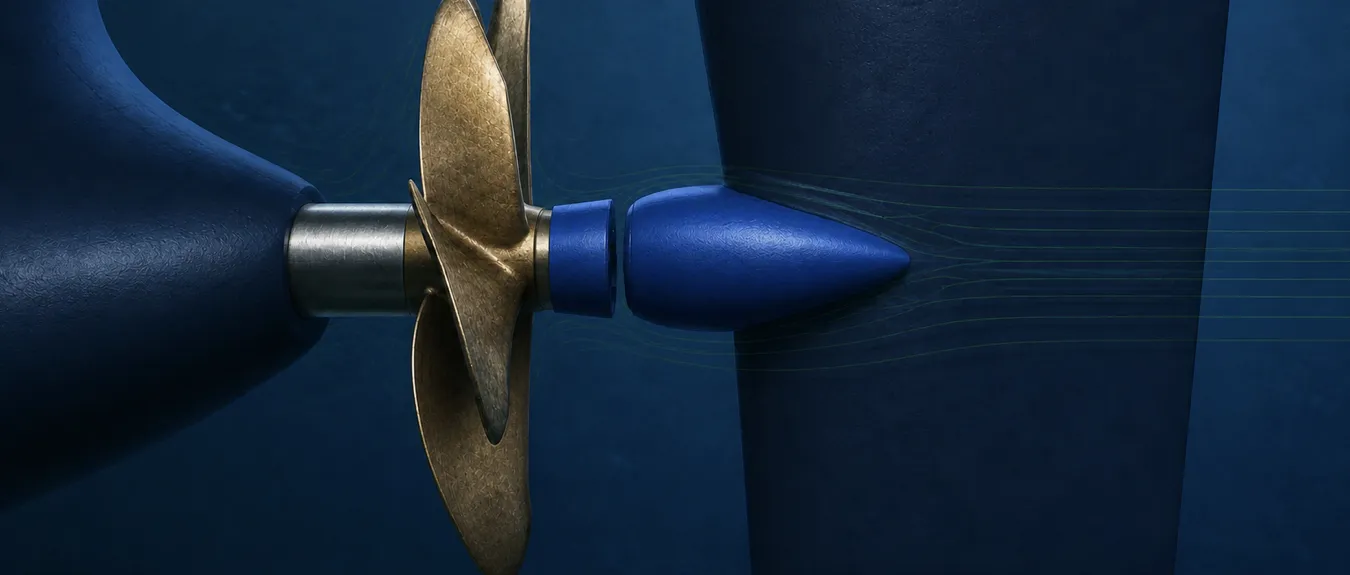
A Rudder Bulb is an Energy Saving Device (ESD) in the form of a streamlined enlargement on the rudder, behind the propeller hub. The bulb influences the hub vortex and the pressure and flow distribution between propeller and rudder. A suitable shape can reduce losses in this region and thus lower the required propeller power at the same ship speed. In suitable applications, a fuel saving of around 1–2% is a realistic indication, with a corresponding reduction in the associated CO2 emissions. The actual benefit is determined by factors including propeller and hub geometry, rudder shape, the distance between them, operating conditions and operational profile. The dimensions and position are matched to these factors, with attention to both propulsion performance and the steering function. In cooperation with a specialist international partner, we support shipping companies, technical managers and shipyards in selecting a Rudder Bulb and coordinating the project, from the initial technical assessment and hydrodynamic analysis through design and engineering, production and delivery to preparation for implementation on board.
Available worldwide
Improving the Flow from Propeller Hub to Rudder
An accelerated, rotating flow develops behind the propeller. Around the propeller hub, vortices may merge into a concentrated hub vortex. The development of this vortex and any flow separation between boss cap and rudder influence the local pressure distribution and the forces on both components.
By matching the bulb shape to the boss cap and rudder, the hub vortex can be weakened and water can flow past the rudder with lower losses. The connection is hydrodynamic: sufficient clearance is still needed between the rotating propeller components and the rudder structure. The assessment also includes pressure and friction forces on the bulb itself. The local flow improvement is thus linked to the combined performance of propeller, boss cap, bulb and rudder.
Matching Bulb Shape, Boss Cap and Clearance
The diameter, length and shape of the bulb are selected in conjunction with the hub diameter, boss cap and front of the rudder. The hub cap, also known as the boss cap, partly determines how water flows towards the bulb. During design, the possible connection with the existing cap and the scope for further flow improvement through a modified cap shape are investigated.
The distance and alignment between cap and bulb influence the development of flow around the hub. A smaller distance may be hydrodynamically favourable. The desired inflow and the space needed for movement are therefore assessed together when making the choice. If the bulb is mounted on the moving rudder blade, it moves with the rudder as the rudder angle changes. Clearance is checked in the straight-ahead position and at the relevant rudder angles.
Propeller geometry, direction of rotation, rotational speed and loading partly determine the flow in which the bulb operates. Draught, trim and ship speed may also change the inflow. The design is therefore assessed under operating conditions that account for an important part of actual service.
When Does a Rudder Bulb Offer Sufficient Hydrodynamic Potential?
A Rudder Bulb may be particularly attractive where hydrodynamic losses in the transition from propeller hub to rudder can be specifically reduced by a modified shape. A concentrated hub vortex, an unfavourable pressure distribution behind the boss cap or a less favourable flow transition to the front of the rudder may justify further investigation of a bulb.
Suitability is therefore determined more strongly by the combination of propeller hub, boss cap and rudder geometry than by ship type alone. Two comparable ships may have different potential for improvement because of differences in hub diameter, cap shape, propeller–rudder distance, rudder profile and operating load.
The space available is also decisive. The bulb must be capable of being positioned close enough to the hub flow from a hydrodynamic perspective while retaining sufficient clearance from the rotating propeller components, both during straight-ahead operation and at the relevant rudder angles. The steering function and load capacity of the rudder remain part of the same design choice.
An initial assessment therefore brings together the existing hub flow, geometric transition to the rudder, clearance and main operating points. It can thus be established early whether optimization with a Rudder Bulb offers sufficient potential, or whether a modification of the boss cap, rudder or another Energy Saving Device addresses the dominant loss more directly.
Retaining the Existing Rudder or Developing the Rudder Geometry Alongside the Bulb
If the existing rudder is retained, bulb shapes that can usefully be incorporated within the available structure and space are investigated. Where the inflow to the front of the rudder also needs improvement, a more extensive modification of the rudder geometry can be investigated. The comparison shows the additional value offered by a bulb or a combined design.
A Twisted Rudder matches the rudder profile to the inflow angle, which varies over the rudder height because of the rotating propeller slipstream. The bulb primarily addresses the region around the propeller hub. When used together, both geometries are matched to each other and the power benefit is established for the complete design.
A Propeller Boss Cap Fins (PBCF) device influences the flow around the hub with fins that rotate with the propeller. A Rudder Bulb forms part of the rudder structure. Both can act on the same hub vortex. The choice between a bulb, a PBCF or a combination therefore depends on the existing cap, rudder and distance between them. The combined effect on power is calculated with attention to the interaction.
The condition of the existing plant is the starting point. If there is heavy fouling or damage, or the propeller is less well suited to the operational profile, the necessary maintenance or modification is established first. That choice provides the basis for assessing the additional improvement around the hub and rudder.
Establishing the Required Power of the Complete Configuration
Computational Fluid Dynamics (CFD) can map the flow behind the propeller and around the boss cap, bulb and rudder. Variants in bulb shape, dimensions and position are compared for their influence on the hub vortex, pressure distribution and hydrodynamic forces. The way in which the propeller is represented in the calculation must reproduce the flow and pressure at the bulb with sufficient accuracy.
For ship performance, the forces on the hull, propeller, boss cap, bulb and rudder are assessed together. At the self-propulsion point, the propulsive and opposing forces are in equilibrium at the ship speed being investigated. The designs with and without a bulb are compared at the same speed and corresponding draught, trim and ship condition. The rudder position is also recorded. The required rotational speed may differ between the two designs. Torque and rotational speed together determine how much power is delivered to the propeller.
If the boss cap or rudder profile is also modified, the components that change in the comparison are recorded in advance. It thus remains clear whether the calculated benefit relates to the bulb or to a more extensive propeller–rudder design. To substantiate bulb performance, propeller operation is assessed in conjunction with the boss cap and rudder.
Assessing Cavitation, Pressure Fluctuations and the Steering Function
A suitable bulb can reduce the hub vortex and associated cavitation. The consequences for cavitation loading at the front of the rudder are also investigated. The influence on cavitation elsewhere on the propeller and rudder is assessed separately where it matters to the project. Local pressures, cavitation phenomena and fluctuating loads are linked to the corresponding operating conditions.
Alongside straight-ahead operation, situations in which rudder loading or the inflow angle changes substantially are investigated. As the rudder angle changes, the flow around the bulb, lateral rudder force and moment needed to operate the rudder change. The design choice therefore combines the expected power benefit with the required steering function and permissible loads on the rudder system. The necessary calculations and tests are tailored to these considerations.
Structural Integration for Retrofit and Newbuilds
The forces on the bulb are transferred through its attachment to the rudder structure. The outer shell, internal stiffeners and connections must be able to withstand these loads. Hydrodynamic shape and structural design are therefore developed together. The consequences for loading on the other rudder components are also assessed.
Where necessary, stresses and deformations are investigated using the method known internationally as the Finite Element Method (FEM). Suitable load cases are used for the bulb, rudder and connections. Fluctuating loads and fatigue are taken into account where they are relevant to the chosen design.
For a retrofit, the existing rudder structure, boss cap, propeller–rudder distance and available access form the starting point. The required reinforcements, installation work and installation sequence are coordinated with the available docking period. For a newbuild, the propeller, boss cap, rudder and bulb can be developed together from an early design stage. In both cases, drawings and calculations are tailored to the ship-specific assessment and applicable classification requirements.
Inspection of the bulb and connections is included in rudder maintenance, with attention to fouling, damage and deformation. If the propeller, boss cap, rudder or operational profile is modified later, hydrodynamic matching and clearance are reassessed. It is also established which previous performance expectations remain usable.
Scale Effects and Verification on the Actual Ship
At model scale, the boundary layer along the hull, propeller inflow and local flow around the hub and rudder differ from those at full scale. The ratio of pressure to friction forces also changes. These scale differences are taken into account when translating model results into the expected power benefit on the ship.
Full-scale calculations can support this assessment. The outcome depends on factors including the turbulence model, computational mesh resolution, propeller modelling and assumed surface roughness. Comparison with suitable model tests or other measurement data helps to assess the calculations. The uncertainty is compared with the predicted power difference and taken into account in the design and investment decision.
After installation, the achieved effect can be assessed using sea-trial or operational data. Measurements of speed, power and rotational speed are linked to draught, trim, loading and relevant weather and sailing conditions. Rudder angles and differences in course-keeping may also influence the comparison. For a retrofit, concurrent work, such as hull cleaning, propeller maintenance and modification of the boss cap, is recorded. The reference and measurement setup reflect whether the bulb alone or the complete modification package is being assessed. Calculated expectations and measured results remain linked to their own conditions and assessment method.
From Power Difference to Annual Fuel Savings
For the annual forecast, the power difference is linked to operating hours at the speeds and loads under which the ship actually operates. Both favourable and less favourable operating points are included. The results are used for the sailing conditions to which they relate. The benefit at the propeller loading and rudder position investigated is thus translated into the expected contribution across the operational profile.
For fuel savings, losses in the drivetrain and the engine’s specific fuel consumption at the changed load are taken into account. The difference in propeller power is thus linked to the consumption of the propulsion plant. The expected CO2 reduction follows from the calculated difference in fuel consumption and the type of fuel used.
The economic assessment covers design, engineering, production, rudder modifications and any boss cap modifications, installation and additional docking time. For a retrofit, these additional costs are distinguished from maintenance that is planned even without the project. The expected saving is assessed over the ship’s remaining period of operation, with attention to maintenance and possible changes in the operational profile. It thus becomes apparent under which operating and cost conditions the improvement around the hub and rudder offers sufficient value for the investment.
Rudder Bulb
In cooperation with a specialist international partner, we support shipping companies, technical managers and shipyards in selecting a Rudder Bulb and coordinating the project, from the initial technical assessment and hydrodynamic analysis through design and engineering, production and delivery to preparation for implementation on board.
Available worldwide
What Is a Rudder Bulb?
A Rudder Bulb is an Energy Saving Device (ESD) in the form of a streamlined enlargement on the rudder, behind the propeller hub. The bulb influences the hub vortex and the pressure and flow distribution between propeller and rudder.
A suitable shape can reduce losses in this region and thus lower the required propeller power at the same ship speed. In suitable applications, a fuel saving of around 1–2% is a realistic indication, with a corresponding reduction in the associated CO2 emissions.
The actual benefit is determined by factors including propeller and hub geometry, rudder shape, the distance between them, operating conditions and operational profile.
The dimensions and position are matched to these factors, with attention to both propulsion performance and the steering function.
Improving the Flow from Propeller Hub to Rudder
An accelerated, rotating flow develops behind the propeller. Around the propeller hub, vortices may merge into a concentrated hub vortex. The development of this vortex and any flow separation between boss cap and rudder influence the local pressure distribution and the forces on both components.
By matching the bulb shape to the boss cap and rudder, the hub vortex can be weakened and water can flow past the rudder with lower losses. The connection is hydrodynamic: sufficient clearance is still needed between the rotating propeller components and the rudder structure. The assessment also includes pressure and friction forces on the bulb itself. The local flow improvement is thus linked to the combined performance of propeller, boss cap, bulb and rudder.
Matching Bulb Shape, Boss Cap and Clearance
The diameter, length and shape of the bulb are selected in conjunction with the hub diameter, boss cap and front of the rudder. The hub cap, also known as the boss cap, partly determines how water flows towards the bulb. During design, the possible connection with the existing cap and the scope for further flow improvement through a modified cap shape are investigated.
The distance and alignment between cap and bulb influence the development of flow around the hub. A smaller distance may be hydrodynamically favourable. The desired inflow and the space needed for movement are therefore assessed together when making the choice. If the bulb is mounted on the moving rudder blade, it moves with the rudder as the rudder angle changes. Clearance is checked in the straight-ahead position and at the relevant rudder angles.
Propeller geometry, direction of rotation, rotational speed and loading partly determine the flow in which the bulb operates. Draught, trim and ship speed may also change the inflow. The design is therefore assessed under operating conditions that account for an important part of actual service.
When Does a Rudder Bulb Offer Sufficient Hydrodynamic Potential?
A Rudder Bulb may be particularly attractive where hydrodynamic losses in the transition from propeller hub to rudder can be specifically reduced by a modified shape. A concentrated hub vortex, an unfavourable pressure distribution behind the boss cap or a less favourable flow transition to the front of the rudder may justify further investigation of a bulb.
Suitability is therefore determined more strongly by the combination of propeller hub, boss cap and rudder geometry than by ship type alone. Two comparable ships may have different potential for improvement because of differences in hub diameter, cap shape, propeller–rudder distance, rudder profile and operating load.
The space available is also decisive. The bulb must be capable of being positioned close enough to the hub flow from a hydrodynamic perspective while retaining sufficient clearance from the rotating propeller components, both during straight-ahead operation and at the relevant rudder angles. The steering function and load capacity of the rudder remain part of the same design choice.
An initial assessment therefore brings together the existing hub flow, geometric transition to the rudder, clearance and main operating points. It can thus be established early whether optimization with a Rudder Bulb offers sufficient potential, or whether a modification of the boss cap, rudder or another Energy Saving Device addresses the dominant loss more directly.
Retaining the Existing Rudder or Developing the Rudder Geometry Alongside the Bulb
If the existing rudder is retained, bulb shapes that can usefully be incorporated within the available structure and space are investigated. Where the inflow to the front of the rudder also needs improvement, a more extensive modification of the rudder geometry can be investigated. The comparison shows the additional value offered by a bulb or a combined design.
A Twisted Rudder matches the rudder profile to the inflow angle, which varies over the rudder height because of the rotating propeller slipstream. The bulb primarily addresses the region around the propeller hub. When used together, both geometries are matched to each other and the power benefit is established for the complete design.
A Propeller Boss Cap Fins (PBCF) device influences the flow around the hub with fins that rotate with the propeller. A Rudder Bulb forms part of the rudder structure. Both can act on the same hub vortex. The choice between a bulb, a PBCF or a combination therefore depends on the existing cap, rudder and distance between them. The combined effect on power is calculated with attention to the interaction.
The condition of the existing plant is the starting point. If there is heavy fouling or damage, or the propeller is less well suited to the operational profile, the necessary maintenance or modification is established first. That choice provides the basis for assessing the additional improvement around the hub and rudder.
Establishing the Required Power of the Complete Configuration
Computational Fluid Dynamics (CFD) can map the flow behind the propeller and around the boss cap, bulb and rudder. Variants in bulb shape, dimensions and position are compared for their influence on the hub vortex, pressure distribution and hydrodynamic forces. The way in which the propeller is represented in the calculation must reproduce the flow and pressure at the bulb with sufficient accuracy.
For ship performance, the forces on the hull, propeller, boss cap, bulb and rudder are assessed together. At the self-propulsion point, the propulsive and opposing forces are in equilibrium at the ship speed being investigated. The designs with and without a bulb are compared at the same speed and corresponding draught, trim and ship condition. The rudder position is also recorded. The required rotational speed may differ between the two designs. Torque and rotational speed together determine how much power is delivered to the propeller.
If the boss cap or rudder profile is also modified, the components that change in the comparison are recorded in advance. It thus remains clear whether the calculated benefit relates to the bulb or to a more extensive propeller–rudder design. To substantiate bulb performance, propeller operation is assessed in conjunction with the boss cap and rudder.
Assessing Cavitation, Pressure Fluctuations and the Steering Function
A suitable bulb can reduce the hub vortex and associated cavitation. The consequences for cavitation loading at the front of the rudder are also investigated. The influence on cavitation elsewhere on the propeller and rudder is assessed separately where it matters to the project. Local pressures, cavitation phenomena and fluctuating loads are linked to the corresponding operating conditions.
Alongside straight-ahead operation, situations in which rudder loading or the inflow angle changes substantially are investigated. As the rudder angle changes, the flow around the bulb, lateral rudder force and moment needed to operate the rudder change. The design choice therefore combines the expected power benefit with the required steering function and permissible loads on the rudder system. The necessary calculations and tests are tailored to these considerations.
Structural Integration for Retrofit and Newbuilds
The forces on the bulb are transferred through its attachment to the rudder structure. The outer shell, internal stiffeners and connections must be able to withstand these loads. Hydrodynamic shape and structural design are therefore developed together. The consequences for loading on the other rudder components are also assessed.
Where necessary, stresses and deformations are investigated using the method known internationally as the Finite Element Method (FEM). Suitable load cases are used for the bulb, rudder and connections. Fluctuating loads and fatigue are taken into account where they are relevant to the chosen design.
For a retrofit, the existing rudder structure, boss cap, propeller–rudder distance and available access form the starting point. The required reinforcements, installation work and installation sequence are coordinated with the available docking period. For a newbuild, the propeller, boss cap, rudder and bulb can be developed together from an early design stage. In both cases, drawings and calculations are tailored to the ship-specific assessment and applicable classification requirements.
Inspection of the bulb and connections is included in rudder maintenance, with attention to fouling, damage and deformation. If the propeller, boss cap, rudder or operational profile is modified later, hydrodynamic matching and clearance are reassessed. It is also established which previous performance expectations remain usable.
Scale Effects and Verification on the Actual Ship
At model scale, the boundary layer along the hull, propeller inflow and local flow around the hub and rudder differ from those at full scale. The ratio of pressure to friction forces also changes. These scale differences are taken into account when translating model results into the expected power benefit on the ship.
Full-scale calculations can support this assessment. The outcome depends on factors including the turbulence model, computational mesh resolution, propeller modelling and assumed surface roughness. Comparison with suitable model tests or other measurement data helps to assess the calculations. The uncertainty is compared with the predicted power difference and taken into account in the design and investment decision.
After installation, the achieved effect can be assessed using sea-trial or operational data. Measurements of speed, power and rotational speed are linked to draught, trim, loading and relevant weather and sailing conditions. Rudder angles and differences in course-keeping may also influence the comparison. For a retrofit, concurrent work, such as hull cleaning, propeller maintenance and modification of the boss cap, is recorded. The reference and measurement setup reflect whether the bulb alone or the complete modification package is being assessed. Calculated expectations and measured results remain linked to their own conditions and assessment method.
From Power Difference to Annual Fuel Savings
For the annual forecast, the power difference is linked to operating hours at the speeds and loads under which the ship actually operates. Both favourable and less favourable operating points are included. The results are used for the sailing conditions to which they relate. The benefit at the propeller loading and rudder position investigated is thus translated into the expected contribution across the operational profile.
For fuel savings, losses in the drivetrain and the engine’s specific fuel consumption at the changed load are taken into account. The difference in propeller power is thus linked to the consumption of the propulsion plant. The expected CO2 reduction follows from the calculated difference in fuel consumption and the type of fuel used.
The economic assessment covers design, engineering, production, rudder modifications and any boss cap modifications, installation and additional docking time. For a retrofit, these additional costs are distinguished from maintenance that is planned even without the project. The expected saving is assessed over the ship’s remaining period of operation, with attention to maintenance and possible changes in the operational profile. It thus becomes apparent under which operating and cost conditions the improvement around the hub and rudder offers sufficient value for the investment.
Approach to Selecting and Developing a Rudder Bulb
In the first project phase, it is established whether the bulb will be added to the existing rudder or form part of a more extensive rudder or propeller design. Any modification of the boss cap is also included. The reference configuration, relevant operating points and necessary substantiation are recorded. The hydrodynamic analysis and bulb geometry are developed further on that basis.
For a promising design, the bulb shape, connection to the rudder and clearance from the rotating propeller components are brought together in the detailed technical design. The proposal describes the components and work included, the operating conditions for which the expected performance is valid and the additional assessments or tests needed. The structural design and documentation are tailored to the chosen arrangement.
After the project decision, production, delivery and preparation for the work on board are coordinated. For a retrofit, the schedule fits the available docking period and other work on the propeller and rudder. If performance verification forms part of the project, the reference data, measurement method and acceptance arrangements are recorded in advance. After installation, the result can then be assessed on the agreed basis.
Have Your Rudder Bulb Project Assessed
Are you considering a Rudder Bulb for your existing rudder or as part of a newbuild project? We would be pleased to discuss the opportunities that the flow between propeller hub and rudder offers for targeted improvement. For a substantive assessment, we would welcome propeller and rudder drawings, boss cap data and an arrangement drawing showing the distance and alignment between them.
Data on the rudder structure, rudder stock position and available rudder angles help to assess integration. Available CFD results, model tests and information on cavitation or vibration can support the technical assessment. Please also mention existing ESDs and planned modifications to the propeller, boss cap or rudder.
For the expected saving, rotational speed, engine or shaft power, ship speed and operating hours for each sailing condition are important, with the corresponding draught, trim and loading. For a retrofit, the condition of the propeller and rudder and the planned docking period are also relevant. During the project discussion, we agree on what further data are needed and how the hydrodynamic and structural design work can fit your ship’s schedule.
Discuss the suitability of a Rudder Bulb for your propeller–rudder configuration >