

How Do You Use CFD to Optimise an Energy Saving Device (ESD)?
Author: Jeroen Berger • Publication date:
Computational Fluid Dynamics (CFD) is used to match the geometry of an Energy Saving Device (ESD) to the flow around the hull, propeller and rudder of a specific ship. Numerical flow calculations can be used to investigate how changes to a Pre-Swirl Stator (PSS), Pre-Duct, Propeller Boss Cap Fins (PBCF) or Rudder Bulb affect propeller operation and hydrodynamic forces. The existing propulsion arrangement provides the starting point. Promising geometries are developed from the calculated inflow, with their shape and position adjusted in stages. The determining factor is not the greatest change in the flow pattern, but the reduction in the shaft power required for the same ship performance. CFD makes it possible to investigate this improvement before a device is built. The reliability of the design choice depends on the ship data, the chosen propeller modelling and the accuracy with which performance differences can be established.
What Data and Assumptions Are Needed for CFD Optimization?
CFD optimization starts with the geometry of the ship and its existing or planned propulsion arrangement. The underwater hull form, propeller geometry, hub construction and rudder arrangement determine how water flows around the stern. Existing appendages can also affect the inflow or the operation of the proposed ESD. For existing seagoing ships, these data are collected from drawings, three-dimensional design models and technical documentation. If the actual configuration differs from these records, additional measurements or a 3D scan may be necessary.
The accuracy of the geometry must be appropriate to the phenomena being investigated. For a Pre-Duct, its position relative to the propeller plane may be important, whereas for a PBCF, details of the boss cap and blade roots play a particularly significant part. A small deviation in the position or shape of a component can affect the local flow. If such differences are not included in the model, the optimization may be based on geometry that does not fully match the ship.
The operating conditions are also established in advance. Ship speed, draught, trim and propeller loading affect the flow around the stern. For a fixed pitch propeller, the geometry and relevant rotational speeds are important. For a Controllable Pitch Propeller (CPP), the blade pitch settings used and the associated operating settings must also be known. The choice of design operating point must suit future operation, because an ESD that performs well at a particular speed does not necessarily retain the same improvement when propeller loading changes.
The physical conditions to be included in the calculation are also determined. The influence of the free surface, for example, may be important to ship resistance and the flow around the stern. For a local flow analysis, a simplified representation may be justified, provided no phenomena that are decisive for the design choice are omitted as a result. The choice between model-scale and full-scale calculations must also be clear in advance.
Before the first ESD is added, the original propulsion configuration is investigated. The flow behind the hull without a working propeller can be calculated, followed by a calculation in which the propeller actually produces thrust. This distinction is important: the nominal wake field behind the hull is not identical to the flow that develops when the working propeller accelerates the water towards it and affects the pressure distribution around the stern.
The reference calculation must describe sufficiently accurately how the hull, propeller and rudder interact under the chosen conditions. The required rotational speed, propeller torque and hydrodynamic forces provide important data for comparison. Where reliable measurement data are available, they are used to investigate how well the calculation describes the original ship performance and relevant flow phenomena.
The reference is decisive for the geometric optimization itself. The orientation of a stator fin, for example, is matched to the local inflow, while the position and profile shape of a Pre-Duct are related to the flow around the stern. If the model predicts an incorrect velocity or pressure distribution there, the selected ESD geometry may also prove unfavourable. Reliable optimization therefore starts with an initial configuration represented with sufficient geometric and hydrodynamic accuracy.
How Does CFD Reveal the Potential for Hydrodynamic Improvement?
Reynolds-Averaged Navier-Stokes (RANS) methods are often used for CFD calculations in ship hydrodynamics. With these methods, the mean flow and the influence of turbulence are described according to a chosen model. The calculations provide velocity fields, flow directions and pressure distributions, among other results. The hydrodynamic forces on the modelled components can also be determined from the pressure and shear stresses.
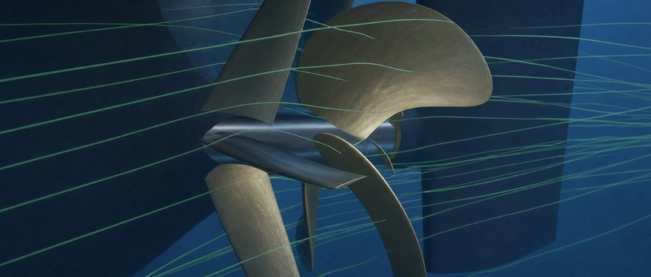
Around the stern, CFD shows how the water reaches the propeller plane and how the working propeller changes the flow. The shape of the stern can produce a non-uniform wake field, causing the propeller blades to encounter different inflow conditions during each revolution. An accelerated, usually rotating propeller slipstream and local vortex structures around the blade roots and hub develop behind the propeller. The flow then reaches the rudder, whose hydrodynamic forces are determined in part by propeller operation.
These results help establish which flow phenomena offer scope for improvement. An unfavourable inflow distribution may prompt an investigation of modified flow guidance. Where controlled pre-swirl can improve propeller operation, a Pre-Swirl Stator offers a different design approach. Behind the propeller, the hub vortex and the flow around the rudder may offer opportunities for a PBCF or Rudder Bulb.
A visible flow phenomenon is not, however, automatically a loss that can be reduced with an ESD. A smaller hub vortex, for example, does not in itself mean that the complete propulsion system operates more efficiently. Nor does a more uniform propeller inflow necessarily provide an improvement if the modified flow is less well matched to the propeller geometry. The forces on the device itself and the response of the other components are also decisive.
The flow analysis is therefore linked to the hydrodynamic forces and the propulsion required. A Pre-Duct can improve propeller inflow while also producing its own drag. A Pre-Swirl Stator can help the propeller operate more favourably, while the stator fins introduce additional losses. CFD helps distinguish these effects and shows which geometric changes warrant further investigation.
The reliability of this diagnosis depends on the numerical model. The computational mesh must be sufficiently fine around profile edges, the propeller hub and areas with steep flow gradients. The treatment of the boundary layer, turbulence and any flow separation also affects the calculated forces. A model suitable for assessing the general flow around a stern may therefore not be accurate enough for the local flow around a small hub device.
The way the propeller is represented in the model also affects which phenomena become visible. A simplified representation may describe the mean acceleration of the water well, but represent certain local vortex structures or fluctuating blade loads inadequately. The flow pattern must therefore always be interpreted within the capabilities of the chosen propeller and turbulence modelling.
How Is the Geometry of an ESD Optimized Through Targeted Changes?
In CFD optimization, the geometric properties that can be adjusted and the improvement sought are first established. Design variants are then analysed numerically to determine how changes in shape and position affect propulsion. The aim is lower power demand within the limits set by the existing ship configuration and technical reliability.
The design variables differ between ESD types. For a Pre-Swirl Stator, the number of fins, fin position, profile shape and local setting angle can be adjusted, among other variables. The fins must generate suitable pre-swirl without causing unnecessarily large losses of their own. CFD shows how a different fin orientation changes the inflow to the propeller blades and which forces develop on the stator.
More pre-swirl is not automatically better. If the local flow direction is not sufficiently well matched to the propeller, blade loading and hydrodynamic losses may actually increase. The optimum stator geometry therefore results from balancing the changed propeller operation against the forces on the stator fins themselves.
For a Pre-Duct, the diameter, position, profile shape and orientation are investigated, for example. Different geometry changes the flow towards the propeller and the pressure distribution on the duct profile. Two variants may therefore provide a similar improvement in propeller inflow while the hydrodynamic forces on the variants differ. The configuration with the most favourable local inflow does not then necessarily have the lowest total power demand.
For a PBCF, the design variables mainly concern the shape, orientation and positioning of the fins on the boss cap. These are matched to the flow behind the propeller blades and around the hub. For a Rudder Bulb, the length, cross-section, contour and connection to the rudder are among the relevant factors. Here, the geometry determines how the flow between the propeller hub and rudder is affected and which forces develop on the bulb and rudder.
Optimization usually proceeds through successive design stages. An initial geometry is analysed numerically and assessed, after which targeted adjustments are made. If, for example, it becomes apparent that a stator fin causes unfavourable loading in a particular area, changing the local setting angle may achieve more than increasing or reducing the size of the entire fin. The next calculation shows whether that adjustment actually enables lower power demand.
Automated parameter studies and numerical optimization methods can be applied in larger design studies. With these methods, multiple combinations of geometric variables are systematically investigated. Simplified models can accelerate the initial exploration, after which the most promising configurations are assessed using more accurate methods. An approximation model based on previous CFD results can also help compare new designs more quickly. The best candidates must then be investigated again using a suitable detailed calculation.
The optimization objective must remain clear. Numerical optimization may, for example, find a geometry that minimizes the calculated power demand at a particular operating point, but that configuration may be structurally unsuitable or perform unfavourably under other operating conditions. Installation space, hydrodynamic loads and other technical constraints are therefore considered during the design stage.
Sensitivity to geometric changes also warrants attention. If a small change in fin orientation or duct position causes a large difference in predicted performance, it must be investigated whether that difference is actually explained by the hydrodynamics or also arises from the numerical method. The optimum found is valid only within the geometries, operating conditions and model accuracy investigated.
When Must the Rotating Propeller Be Modelled in Detail?
The way the propeller is described in CFD has a major influence on the flow calculated at an ESD. The working propeller changes not only the water velocity, but also the pressure distribution around the stern and the properties of the propeller slipstream. The accuracy required therefore depends on which interaction is decisive for the design.
A simplified propeller representation may be sufficient for an initial exploration. In an actuator disk model, for example, the influence of the propeller is represented as a distribution of forces in the region of the propeller plane. Depending on how the model is implemented, both axial loading and the influence on flow rotation can be included. The individual propeller blades do not have to be fully represented in the computational mesh for this purpose.
This approach can reduce computation time and is useful for certain investigations of the general inflow and propeller–hull interaction. Its accuracy does, however, depend on the force distribution used and the way the propeller model interacts with the flow calculation. An actuator disk model that does not describe a tangential force distribution, for example, is less suitable for an assessment centred on propeller slipstream rotation.
Another option is to couple a separate propeller model to the CFD calculation. A hydrodynamic calculation method for the propeller can then process the local inflow and pass the resulting forces to the flow model. This can produce a more detailed representation of propeller operation without every blade having to be resolved directly in a fully viscous CFD model. The suitability of this approach depends on the coupling used and the flow phenomenon being investigated.
For a PBCF, the local flow behind the blade roots is particularly important. The hub fins rotate with the propeller and affect vortex structures directly related to the blade geometry. A propeller model that provides only a mean force distribution may contain insufficient detail for this interaction. In certain stator and rudder designs, the spatial distribution of propeller loading may also be decisive for the result.
In a direct propeller calculation, the actual blade geometry is included in the CFD model. A steady-state approach with a rotating reference frame may be useful for certain design questions. Where the changing position of the blades relative to the wake field or other components is important, a time-dependent calculation with a propeller mesh that actually rotates may become necessary. Fluctuating pressure distributions and loads can also be investigated in this way.
This additional detail requires more computing capacity and places greater demands on the computational mesh, the coupling between moving and stationary computational domains, and the numerical settings. A direct calculation is also not automatically more reliable if the geometry, mesh quality or modelling is insufficiently accurate. The choice of model must therefore be matched to the required prediction accuracy and the relevant hydrodynamic mechanism.
Different levels of modelling can be used alongside one another for efficient optimization. A simplified representation helps identify promising geometries, while a more detailed calculation investigates the most important local interactions. Before small performance differences become decisive, however, it must be clear whether the chosen method is accurate enough to establish those differences reliably.
How Does a Self-Propulsion Calculation Determine the Power Saving?
The hydrodynamic performance of an ESD is ultimately assessed on the basis of the shaft power required to propel the ship under the same conditions. The forces on the hull, propeller, rudder and added device must therefore be considered together. An ESD can improve propeller operation while also producing a hydrodynamic force of its own that affects the net benefit.
In a self-propulsion calculation, the operating point at which the propulsive and opposing forces are in balance is sought. This can be done, for example, by adjusting the propeller rotational speed in successive calculations until the required force balance at the chosen ship speed is achieved with sufficient accuracy. In a model-scale calculation, additional forces or corrections may be needed to account for the difference from full-scale resistance.
When an ESD is added, the propeller may require a different rotational speed at the same ship speed. The torque required may also change. Shaft power follows from the combination of these two quantities. Higher propeller thrust at the same rotational speed therefore does not yet demonstrate a power saving. Torque may also increase, and the modified flow may produce different forces on the hull, ESD and rudder.
A comparison between two Pre-Duct designs illustrates this distinction. The first duct may substantially change the speed and direction of the propeller inflow, but cause significant hydrodynamic losses of its own in doing so. A second design may affect the inflow less strongly and still perform more favourably because losses on the duct profile remain smaller. The self-propulsion calculation shows which configuration ultimately requires less shaft power for the same ship performance.
For this comparison, the reference and design variants must be evaluated by calculation under equivalent conditions. The speed through the water, draught, trim and other relevant assumptions remain the same. The chosen treatment of the free surface, ship motions and scale corrections must also be sufficiently consistent. Rotational speed and torque may differ, because it is precisely the changed propeller operation that is being investigated.
For a CPP, a different combination of blade pitch and rotational speed may also be favourable. The control strategy used and the optimization permitted must then be treated consistently across the configurations under investigation. Otherwise, a calculated performance difference may arise partly from modified propeller control rather than solely from the added ESD.
The numerical accuracy of the comparison also warrants attention. Where an ESD provides a small power reduction, the calculations with and without the device must be sufficiently accurate and comparable with one another. Good agreement between the calculated and measured initial performance is valuable, but does not automatically demonstrate that the calculated difference after the ESD is added is equally reliable.
The calculated power reduction represents the predicted hydrodynamic performance of the design under the conditions concerned. That result is not automatically equal to the eventual fuel saving. Engine operation and any coupled systems also matter to that outcome. Within CFD optimization, the change in shaft power demand remains the principal measure for assessing whether the geometric adjustment can actually provide a benefit.
How Is an ESD Optimized for Different Operating Conditions?
An ESD is usually developed with a fixed geometry, while the inflow and propeller loading change during operation. A design that provides the greatest power saving at the nominal cruising speed therefore does not automatically deliver the best performance across the full operational profile. Promising geometries are consequently investigated under the most important operating conditions. For a coastal tanker that alternates between laden and ballast operation, for example, different draughts and propeller loads may be relevant. For a seagoing ship that consistently operates within a limited speed range, the emphasis may instead be more strongly on a particular operating range. The chosen conditions must match the operation for which the device is being designed.
This assessment can influence the geometric optimization. A Pre-Swirl Stator with the greatest improvement at an individual operating point need not remain the preferred choice if a slightly different fin orientation performs more favourably under several frequently encountered conditions. A Pre-Duct may also be sensitive to changes in propeller loading, as the pressure distribution on the duct profile and the interaction with the propeller shift.
The design can therefore be optimized for a set of representative operating points. What matters is how much shaft power a geometry saves under each condition and how many operating hours the ship is expected to spend in those conditions. A design with a higher percentage saving in an infrequently used operating condition therefore does not necessarily provide the greatest energy saving over the course of operation.
Possible adverse effects are also investigated. Modified propeller inflow can affect susceptibility to cavitation and fluctuating blade loads. For a Rudder Bulb, rudder operation at the relevant angles warrants attention. A conventional RANS calculation of the mean flow can provide indications, but without additional modelling it does not describe all the phenomena important to cavitation, vibration and manoeuvrability.
Geometric optimization must therefore distinguish between the operating points at which energy savings are sought and the conditions under which the ESD must continue to function in a technically sound manner. Not every operating condition needs to carry equal weight in the energy-saving calculation, but the device must remain suitable for the relevant loads and necessary manoeuvres.
How Are the Accuracy and Reliability of CFD Results Assessed?
CFD optimization produces calculated results, not directly measured savings for the ship. It must therefore be established how reliable the numerical prediction is and which uncertainties influence the choice between different geometries.
During numerical verification, the calculated solution is examined to establish whether it is sufficiently accurate for the chosen mathematical model. A mesh study can, for example, show how the calculated forces and propeller torque change when the computational cells are refined. Convergence of the calculation is also important. Not only are the numerical residuals assessed, but so too is the stability of the quantities on which the design choice is based.
In time-dependent calculations, the time step and simulation duration also play a part. If the loading on the propeller blades changes during each revolution, the relevant phenomena must be described with sufficient accuracy over time. A stable mean result does not in itself provide sufficient certainty about the magnitude of fluctuating loads.
Validation has a different function. Here, the degree of agreement between the numerical model and physical measurements is investigated. Resistance and propulsion tests, pressure measurements and flow measurements may, for example, be useful for an ESD project. The comparison must concern sufficiently similar geometries and operating conditions, with measurement uncertainty also taken into account.
When a CFD model predicts the original ship performance well, this supports the reliability of the reference. It does not, however, automatically demonstrate that the same accuracy is retained after an ESD is added. The device may introduce local flow phenomena that are inadequately described by the original model. The changes in flow, forces and power caused by the ESD therefore warrant particular additional scrutiny.
An important consideration is that different numerical methods can produce divergent performance predictions for the same ESD. The calculation of the wake field and the way the working propeller is modelled can be particularly influential. A more detailed model offers scope to describe more hydrodynamic phenomena, but does not remove the need for numerical verification and experimental validation.
Scale effects warrant separate attention. The boundary layer along the hull, the wake field distribution and the flow around an ESD may differ between model-scale and full-scale conditions. For devices that generate pre-swirl, the axial and tangential changes in inflow warrant separate attention. A favourable improvement at model scale therefore cannot be adopted directly as full-scale performance without a sound assessment.
For the final design choice, what matters most is whether the calculated performance difference is sufficiently reliable. Two designs may show different power savings, while the difference cannot reliably be distinguished from the uncertainty associated with those performance predictions. In that case, it has not yet been convincingly demonstrated which geometry is hydrodynamically better. This does not mean that both designs have exactly the same performance. It means that the available information provides insufficient certainty for the calculated advantage to be decisive. Additional calculations or tests may then be worthwhile if an uncertainty that determines the decision can be reduced in this way. If performance remains comparable, structural simplicity and maintainability may carry more weight.
The uncertainty assessment can therefore determine which geometry is developed further, which additional calculation is needed and when the design is sufficiently substantiated to proceed to the next engineering stage.
What Does CFD Ultimately Deliver for ESD Design?
Carefully conducted CFD optimization produces a technically substantiated ESD geometry, with insight into the flow phenomena that explain its predicted operation. The design study shows which shape and position are preferred, under which conditions a power saving is expected and which uncertainties accompany that prediction.
The hydrodynamic loads relevant to further structural development also become clear. For a Pre-Swirl Stator or Pre-Duct, these concern, for example, the selected profile geometry, position and forces on the supporting structure. For a PBCF, matching the device to the propeller hub and positioning the fins are important. For a Rudder Bulb, the contour and connection to the rudder must suit the available space and local flow.
The design output must also record sufficiently clearly which ship geometry, operating conditions and propeller modelling have been used. The reference without an ESD and the calculated power differences must also remain identifiable. Without these data, another design variant cannot be compared reliably, and it is difficult to establish the basis of the predicted improvement.
The results provide the starting point for further engineering. Hydrodynamic calculations do not automatically provide all the data needed for the final approval of a structure. Depending on the configuration, additional strength calculations, investigations of fluctuating loads and checks of the attachments may be necessary.
For promising designs, model tests can further substantiate the calculated performance. The influence of scale effects on the expected power saving can also be investigated. After installation, suitable sea trial or performance measurements can help establish the extent to which the predicted improvement is achieved during operation. The separate contribution of the ESD must remain identifiable if other modifications to the hull or propulsion arrangement have been made at the same time.
CFD thus makes it possible to develop an Energy Saving Device specifically for the existing or planned propulsion configuration. Starting from a reliable reference, relevant flow phenomena are investigated, geometric design variants adjusted and performance compared under equivalent conditions. The best configuration is not necessarily the one with the greatest local change in flow, but the geometry that reduces the ship's power demand with sufficient reliability and can be built and used on a sound technical basis.
This Article in the Series
CFD optimization builds on the assessment of whether maintenance, propeller optimization or an additional ESD offers the greatest potential for improvement. To assess the calculated power improvement reliably at a later stage, suitable operating conditions for the assessment of ESD performance are important. The relationship between design calculations, performance comparisons and measurements is central to hydrodynamic design and performance validation of ESDs.