

Hydrodynamic Design and Performance Validation of Energy Saving Devices (ESDs) for Ships
A hydrodynamic design study helps match an Energy Saving Device (ESD) to the flow around the hull, propeller and rudder. The choice of a suitable ESD configuration guides the investigation; the results may further refine that choice. Computational Fluid Dynamics (CFD) makes it possible to improve shape and placement before a device is built. Calculations and suitable measurements must then establish what power benefit can be expected under the conditions investigated. Comparing design variants requires different information from confirming performance after installation. A suitable reference also makes clear whether the result describes the individual ESD or a broader modification to the propulsion system.
Developing Promising ESD Geometries with CFD
The computational model describes the existing or planned hull, propeller and rudder geometry. The boss cap, existing appendages and distances between components are included where they influence the flow being investigated. The propulsion system without the ESD now under investigation forms the reference. For a retrofit, the drawings and models must correspond sufficiently closely to the actual configuration.
A CFD optimization of an Energy Saving Device (ESD) uses the calculated flow and forces to make targeted adjustments to shape and position. For a Pre-Swirl Stator (PSS) or Pre-Duct, this may involve, for example, the fin angle or duct profile. For Propeller Boss Cap Fins (PBCF), the flow around the blade roots and boss cap requires sufficient detail; for a Rudder Bulb, the transition to the rudder is important. The propeller modelling must be able to describe these key interactions. A simplified model can support an initial selection, after which the most promising geometries are investigated in greater detail if necessary.
Assessing the Power Demand of the Complete Propulsion System
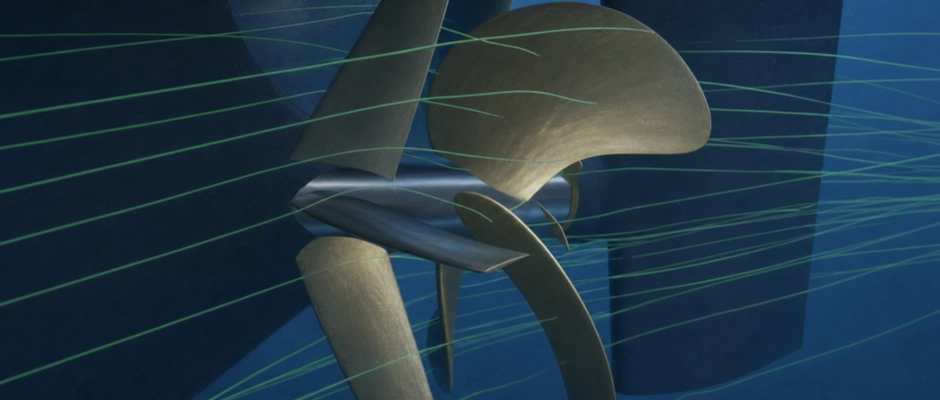
Flow visualizations explain where a design can offer improvement, but do not provide a measure of the saving on their own. Improved propeller performance can coexist with additional drag on the device or a change in rudder loading. Under suitable conditions, a Pre-Duct can itself provide a forward force. To assess the effect of an ESD on overall propulsion performance, these contributions must be included in the same comparison.
For this purpose, the self-propulsion point is determined: the condition in which the propulsive and opposing forces are in balance at the chosen speed. The configurations are compared in terms of the corresponding shaft power at the same speed through the water, draught, trim and other relevant conditions. Rotational speed and torque may differ, because the ESD can change the propeller performance and the balance of forces.
Comparing Design Variants Across the Actual Operational Profile
A common reference and equivalent design assumptions are needed for the comparison of ESD designs under representative operating conditions. For a Controllable Pitch Propeller (CPP), the opportunities to optimize blade pitch and rotational speed are treated consistently across the configurations being compared. It also remains clear whether only the ESD changes or whether a new propeller or different control forms part of the alternative.
The power differences at each operating point are linked to the corresponding operating hours. Conditions in which a design requires additional power also count. The ranking across the operational profile may therefore differ from that at the nominal cruising speed. Where the ship alternates between laden and ballast operation, what matters is which design saves the most propulsion energy over the expected service and whether that preference holds when the distribution of operating hours changes.
A small calculated advantage is decisive only when the difference can be distinguished with sufficient confidence. If that remains uncertain, no clear hydrodynamic preference has yet been demonstrated. Feasibility, acceptable loads and sufficient manoeuvrability also remain conditions for application, even for a design that requires less power on average.
Using CFD and Additional Measurements to Substantiate ESD Performance
Numerical verification and physical validation answer different questions. Verification examines the accuracy of the computational solution, for example through mesh refinement, convergence and the time step in time-dependent calculations. Validation compares the prediction with physical measurements. An accurate prediction of the original shaft power supports the reference, but does not in itself demonstrate that the power difference after adding an ESD is calculated equally accurately.
The uncertainty that still needs to be reduced for the design choice determines when additional measurements are needed alongside CFD to verify ESD performance. Existing model tests or measurements may be useful where the geometry, operating conditions and key flow phenomena are sufficiently similar. New investigations are selected on the basis of the missing information. A propulsion test examines the combined performance; flow and force measurements test specific aspects of the calculated behaviour. Cavitation, pressure pulses or vibration may require a different test setup from that used to assess the average power difference.
Model results require a sound extrapolation to full scale because, among other factors, the boundary layer and wake field differ. Full-scale calculations support that assessment, but remain dependent on the models and input data. A sea trial can test the prediction against the actual ship. Performance monitoring can additionally show how performance develops in service, within the limits of the available reference and data quality.
The Right Operating Conditions for Reliable Performance Measurements
An onboard measurement must correspond sufficiently closely to the conditions for which the saving was predicted. Speed, draught, trim, water depth and weather effects can change power demand. Where there is a current, speed over the ground and speed through the water must be distinguished. Calm conditions and stable measurement periods help limit the magnitude of the corrections required.
A suitable measurement setup combines the right operating conditions for ESD performance measurements with accurate, synchronized measurement data. The speed range, loading and permitted corrections are specified in advance. Torque, rotational speed and speed are recorded on the same time basis; for a CPP, blade pitch also forms part of those data. Uncertainty in the instruments and corrections partly determines how accurately a small power difference can be established.
Distinguishing the ESD Contribution from Other Improvements
Measurement accuracy and attribution of the result are separate requirements. When the hull is cleaned, the propeller is polished and an ESD is installed during the same docking, the subsequent measurement describes the combined configuration. To establish the individual ESD contribution, it must be known how the ship would have performed after the same maintenance but without the device.
The other work therefore also helps determine the basis of comparison for the individual ESD effect. That reference warrants attention before the work begins. If there is no direct reference measurement, calculations and other performance data can support the assessment. The ESD contribution derived from these remains a model-supported estimate. A measured overall improvement remains valuable, provided it is clear which measures are included and which share can be substantiated separately.
From Performance Evidence to Further Engineering
A useful design outcome describes the selected geometry, the operating points investigated, the expected power differences and the associated uncertainties. The calculated loads must also be available for further development. We help align the hydrodynamic assessment and any performance measurements with the project requirements, in cooperation with a specialist international partner. Thus, the investigation aligns with the performance that needs to be substantiated for the design decision or after installation.
The design data are then used to assess the technical integration of ESDs and the requirements throughout their service life. Structural engineering builds on this and investigates which additional loads and checks are needed. Assessing fuel savings and economic value also requires data on engine operation, future service and project costs.