

Why Must the Effect of an ESD Be Assessed in Terms of Overall Propulsion Performance?
Author: Jeroen Berger • Publication date:
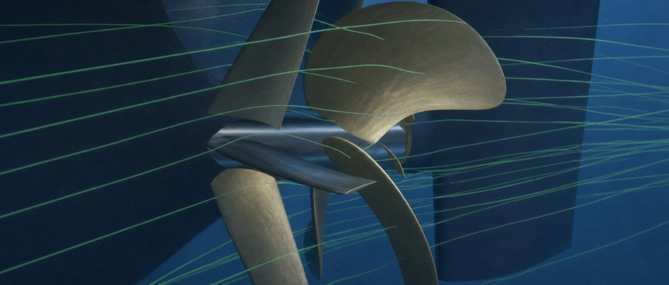
The effect of an Energy Saving Device (ESD) must be assessed in terms of overall propulsion performance, because better propeller operation does not automatically produce an equally large reduction in the shaft power required. A Pre-Swirl Stator (PSS), Pre-Duct, Propeller Boss Cap Fins (PBCF) or Rudder Bulb changes the flow around the propeller. The hydrodynamic forces on the hull, rudder and device itself may therefore also change. A favourable effect on the propeller may be partly offset by additional losses elsewhere. Conversely, an ESD can reduce total power demand by providing a favourable force of its own, even when the individual propeller efficiency barely improves. The actual contribution arises from the combined operation of all the components involved. Flow changes and individual efficiencies are therefore investigated, as is, above all, the shaft power that the complete configuration needs for the same ship performance.
Why Does Better Propeller Operation Not Yet Prove a Power Saving?
The efficiency of a ship propeller can be assessed in different ways. In an open-water test, an assessment is made of how the propeller delivers thrust under uniform inflow in relation to the power absorbed. Behind a ship, the same propeller operates in the hull's wake field. The flow is distributed differently there, and the working propeller also affects the pressure distribution around the stern.
Open-water efficiency and the performance of the propeller behind the ship are therefore not the same. Moreover, neither describes all the hydrodynamic contributions to propulsion on its own. Interaction with the hull, rudder and any additional devices also determines how much power is needed to propel the ship.
In a traditional propulsion analysis, this interaction is described using factors including effective wake, thrust deduction and relative rotative efficiency. The wake describes the influence of the hull on the effective propeller inflow. Thrust deduction is related to the change in the forces on the ship caused by the working propulsion system. Relative rotative efficiency compares the propeller torque required in open water with the torque behind the ship at corresponding thrust and rotational speed. An ESD can affect several of these factors at once. For a combined propeller–ESD configuration, it must also be clear how the individual forces have been accounted for in the efficiency figures used.
A Pre-Swirl Stator shows why this distinction matters. The fixed fins change the direction in which the water reaches the propeller. The relative inflow angles and the distribution of blade loading may therefore become more favourable. Under certain conditions, the propeller can then provide the required propulsion while absorbing less power. This does not mean that the open-water characteristic of the original propeller geometry itself has changed. The improvement may instead arise from the different inflow in which the same propeller operates behind the ship.
The stator fins themselves, however, experience hydrodynamic forces. Depending on the geometry and inflow, the component of those forces in the direction of travel may be favourable or unfavourable. The changed propeller operation may also affect the forces on the stern. If these effects are not included, the propeller improvement may give an incomplete picture of the result for the ship.
The reverse is also possible. Under suitable conditions, a Pre-Duct can provide a favourable forward force component. Total power demand may therefore fall even when the propeller itself shows only a limited efficiency improvement. The improvement then arises partly because the device changes the distribution of propulsive and opposing forces.
A lower propeller torque or a higher thrust figure also does not, in itself, prove an energy saving. The shaft power required is related to both torque and rotational speed. The propeller must also provide sufficient propulsion to balance the forces on the complete ship configuration.
Individual propeller efficiency remains valuable for understanding how a design works. A broader assessment is, however, needed to make a statement about the ship's energy saving. The question is not only whether the propeller operates more efficiently, but whether the complete configuration requires less power for the same ship performance.
Which Forces on the Hull, ESD and Rudder Must Count?
An ESD affects propulsion through the flow and forces on different components. The contribution of the device depends in part on where the forces arise and how they are transmitted to the ship.
For a Pre-Duct, the water flow ahead of the propeller is guided by the duct profile. The pressure distribution on the profile causes a hydrodynamic force that is transmitted to the ship structure through the attachment. At the same time, the propeller inflow changes. The required rotational speed, torque and delivered propeller thrust may therefore change.
The influence is not necessarily limited to the duct and propeller. The modified inflow and propeller operation can also change the pressure distribution on the stern. The hydrodynamic force on the hull may therefore differ from that of the original configuration. A comparison dealing only with the separate forces on the duct and propeller may miss this contribution.
A similar interaction occurs with a Pre-Swirl Stator. The stator fins affect the propeller inflow direction, but transmit their own hydrodynamic forces to the hull through the attachment. The combined performance therefore depends on the changed propeller operation, the stator forces and the response of the other ship components.
For a Propeller Boss Cap Fin, force transmission is different. The PBCF rotates with the propeller hub. The hydrodynamic forces and moment on the hub fins therefore form part of the loading on the rotating propeller structure. When the thrust and torque of the complete rotating configuration are determined, it must be clear whether the PBCF contribution is already included. Otherwise, the same contribution may inadvertently be counted twice or left out of the assessment.
This distinction is also important in model tests and numerical calculations. A measurement of the propeller blades alone need not include the same force components as a measurement of the complete propeller with its boss cap and PBCF. When comparing research results, it must therefore be known which surfaces and components have been included in the reported thrust and torque.
A Rudder Bulb, by contrast, forms part of the rudder. The bulb changes the flow and pressure distribution around the front of the rudder, while the resulting forces are transmitted through the rudder structure. The flow around the propeller hub may also change as a result. The influence on the rudder and propeller must therefore be assessed together.
A rudder need not produce only an opposing force, and this warrants attention. Under certain conditions, a suitably designed rudder can affect the rotating propeller slipstream in such a way that a forward force component develops. When an ESD changes the properties of the propeller slipstream, this contribution may also change. The direction and magnitude of the resulting force depend on the rudder geometry, rudder position and local inflow.
For the hydrodynamic assessment, a consistent definition of the component boundaries is therefore needed. Forces on the hull, fixed devices, rotating propeller configuration and rudder must be accounted for in such a way that all relevant contributions count, without counting the same force more than once. The forces and moments must come from the same physical configuration and the same operating point.
The individual forces then help explain why an ESD works. The combined effect of those forces determines the shaft power the ship needs.
How Can a Favourable Flow Change Still Produce a Disappointing Result?
An ESD is often developed around a flow phenomenon that offers opportunities for improvement. This may be non-uniform propeller inflow, residual rotation in the propeller slipstream or a pronounced hub vortex. When a device changes such a phenomenon favourably, it has not yet been established how much energy is actually saved.
Consider a hypothetical design study for a seagoing bulk carrier in which a Pre-Duct is being investigated. An initial design produces clearly more uniform propeller inflow. The propeller responds favourably, but relatively large opposing hydrodynamic forces develop on the duct profile. A second design changes the inflow less strongly, but has a more favourable force distribution of its own.
The second design may therefore ultimately require less shaft power despite the smaller local flow change. The result depends on the complete propulsion system, rather than solely on the extent to which the inflow becomes more uniform. Moreover, a uniform wake field is not, in itself, an optimum design objective when the existing propeller geometry benefits from a particular distribution of speed or direction.
Another example concerns the flow around the propeller hub. A PBCF can influence the development of the hub vortex and thereby improve propeller operation. The modified flow also reaches the rudder behind it, however. If rudder drag increases as a result, part of the improvement may be lost.
This effect has been established in experimental and numerical research into PBCFs in propeller–rudder arrangements. In the configurations investigated, the presence of the PBCF led to higher rudder drag, reducing the net improvement of the propeller–rudder arrangement. The magnitude and direction of this interaction depend on geometry and operating conditions. The research result therefore does not mean that every PBCF increases rudder drag.
A smaller hub vortex is also not a direct measure of the total energy saving. A vortex structure may diminish locally while other flow losses increase. Conversely, an ESD can improve propeller loading and the distribution of hydrodynamic forces without all visible vortex structures disappearing.
Flow patterns and individual efficiencies are therefore particularly valuable as a technical explanation. The results show where operation changes and can help improve a geometry further. The decisive performance indicator remains the power demand of the complete ship configuration.
Why Is the Self-Propulsion Point Decisive for the Actual Saving?
At a constant ship speed, the propulsion system must provide sufficient force to overcome the opposing forces on the ship. The self-propulsion point is the operating condition in which this force balance is achieved. The corresponding propeller rotational speed and torque determine how much power the propeller absorbs.
When an ESD is added, the force balance may change. A device can produce a forward or opposing force of its own, affect propeller inflow and alter the pressure distribution on the hull or rudder. The propeller therefore need not deliver the same thrust as in the reference configuration without an ESD.
This has implications for the way the power saving is established. A comparison at the same rotational speed may, for example, show that a propeller with an ESD delivers more thrust. But if, as a result, the ship does not have the same force balance at that setting as the reference, the two calculations do not describe equivalent self-propulsion performance.
For a reliable comparison, the appropriate self-propulsion point is therefore determined for each configuration. Ship speed through the water, draught, trim and relevant environmental conditions are kept the same. Rotational speed is then adjusted where necessary until the force balance is achieved with sufficient accuracy. Power demand follows from the corresponding rotational speed and torque.
In model tests or model-scale Computational Fluid Dynamics (CFD) calculations, a correction may also be needed for the difference in skin-friction resistance between the model and the full-scale ship. Extrapolation of the modified inflow also warrants separate attention for certain ESD types. A self-propulsion point established at model scale is therefore not equivalent to the operating point of the completed ship without further assessment.
For a Controllable Pitch Propeller (CPP), blade pitch becomes an additional variable. The required propulsion can be provided through different combinations of blade pitch and rotational speed, depending on the installation and control strategy. Where the ESD makes a different combination favourable, it must be clear which settings and optimization options are permitted in the comparison. This distinction prevents an improvement due to modified CPP control from being inadvertently attributed entirely to the ESD. Where the new control forms part of an integrated optimization, the overall performance of that configuration can be assessed. The reported improvement must then relate to the complete modification investigated.
The location at which power is determined also warrants attention. The power absorbed by the propeller and the shaft power measured at another point in the drivetrain need not be exactly equal where mechanical losses or coupled power take-offs play a part. For the comparison, it must therefore be clear which power quantity is being used and whether it has been established on the same basis for both configurations.
The self-propulsion point thus connects local hydrodynamic changes with the actual performance of the ship. Neither an individual force nor favourable propeller efficiency determines the saving; the power that the complete configuration needs for the same ship performance does.
What Does Overall Propulsion Performance Mean for ESD Assessment?
A technically substantiated ESD assessment must answer two questions. What hydrodynamic changes does the device cause? And how much power does the ship save when all their relevant consequences are included?
For the first question, flow patterns, pressure distributions and forces on individual components are valuable. These results may, for example, show that a stator fin causes locally unfavourable pre-swirl or that a hub device increases rudder drag. It thus becomes clear where further design changes are worthwhile.
The second question requires a comparison of overall propulsion performance. For this purpose, it is established how much shaft power the reference configuration and the version with an ESD need at the same speed and ship condition. The difference constitutes the predicted or measured power saving under those conditions.
A useful technical result also makes clear which changes have been included in the assessment. For a separate ESD on the existing propeller, it must be clear what the added device changes. Where the propeller geometry, rudder or CPP control is modified at the same time, the calculated benefit describes a more extensively modified propulsion configuration. That overall improvement must not be attributed solely to the ESD without further substantiation.
The reliability of the power difference also remains important. A small calculated improvement may be technically valuable, but must be established with sufficient accuracy to support a convincing conclusion. The chosen calculation or test method must therefore be suitable for the flow phenomena that the ESD concerned affects. A good prediction of the original shaft power does not automatically prove that the change after adding the ESD is determined with the same accuracy.
The power improvement may also differ between operating conditions. A device that performs favourably at the nominal cruising speed need not provide the same contribution at a different draught or propeller loading. For a seagoing ship with varying loading or a wide speed range, it must therefore be clear under which conditions the net improvement is maintained. The eventual energy saving across the operational profile follows from the power differences and the corresponding operating hours.
Favourable power demand is, finally, not the only technical criterion. The modified flow may also affect cavitation, vibration, structural loads and manoeuvrability. These effects must remain technically acceptable within the required operating range. A device that requires less power during straight-ahead operation may therefore still need design changes before its application is technically justified.
The hydrodynamic improvement must also be distinguished from the eventual fuel saving. The amount of fuel saved through a reduction in shaft power depends on factors including engine load, specific fuel consumption and any coupled systems. A percentage power saving must therefore not automatically be presented as the same percentage fuel saving.
The effect of an Energy Saving Device must be assessed in terms of overall propulsion performance because the device can change the forces and flow around several components at once. Favourable propeller operation or a local flow improvement is a valuable indication, but does not constitute proof of an energy saving on its own. The decisive comparison shows how much power the complete configuration needs under equivalent conditions and whether the reduction has been established with sufficient reliability. It thus becomes clear where the improvement comes from and what contribution actually remains for the ship.
This Article in the Series
In the comparison of ESD designs under representative operating conditions, the question of which version can save the most propulsion energy across the operational profile is investigated. Where lower power demand is measured after installation, a suitable comparison basis for the separate ESD contribution is also needed to distinguish the influence of any other work. The relationship between design choice, performance comparison and supporting evidence is central to hydrodynamic design and performance validation of ESDs.