

When Is Finite Element Analysis (FEA) Technically Appropriate for the Structural Integration of an ESD?
Author: Jeroen Berger • Publication date:
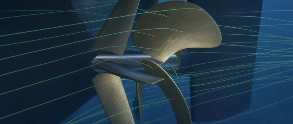
FEM analysis is technically appropriate when the strength, stiffness, stability or fatigue resistance of an Energy Saving Device (ESD) and its attachment structure cannot be demonstrated with sufficient reliability using simpler calculations. With the Finite Element Method (FEM), an assessment is made of how loads are transferred through the structure and where critical stresses or deformations arise. This is particularly relevant to a Pre-Swirl Stator (PSS), Pre-Duct, Propeller Boss Cap Fins (PBCF) device or Rudder Bulb with complex load transfer, local stress concentrations or components that experience fluctuating forces over long periods. Computational Fluid Dynamics (CFD) can help establish hydrodynamic loads, but does not directly indicate whether the structure can withstand them. FEM links these loads to the geometry, material properties and support of the device. Which analysis is needed depends on the structural risks, available load data and applicable design requirements. An unusual operating condition may govern the design, even if the ESD performs favourably hydrodynamically at normal cruising speed.
When Is a Simple Strength Check Sufficient, and When Is FEM Needed?
Structural assessment starts with how an ESD is loaded and how the forces are transferred to the ship. For a straightforward structure, analytical calculations and applicable design rules may be sufficient to check the strength of individual components or connections. A simple attachment with a well-understood load does not automatically require an extensive FEM model.
That changes when the actual stress distribution can no longer be described with sufficient reliability using such simplifications. A Pre-Swirl Stator, for example, experiences hydrodynamic forces that cause bending and torsion in the fins. The connection to the stern must transfer these loads to the shell plating and stiffeners behind it. The strength of the fin matters, as does local loading on the hull structure.
A stator fin may be sufficiently strong on its own, while high stresses or undesirable deformations arise around the connection. The fin support and the stiffness of the stern influence each other. FEM can provide insight into this relationship when a simple calculation offers insufficient certainty about the actual load transfer.
This deserves particular attention on existing seagoing ships. The existing structure was usually not originally designed for the additional ESD loads. It may therefore be necessary to investigate the shell plating, stiffeners and adjoining structural members as well. A calculation covering only the ESD itself then provides an incomplete picture of structural suitability.
Maximum material stress is not the only potential governing factor. A relatively slender duct structure may, for example, be susceptible to local instability, while fatigue life may become decisive for a welded stator attachment. Deformation that remains within the allowable material stress may also be unacceptable if the clearance from the propeller or rudder consequently becomes insufficient.
The possible consequences of structural failure also matter. If an insufficiently strong connection could cause damage to the stern, loss of a component or danger to the propeller and rudder, the assessment must provide sufficient certainty about the relevant loads and failure mechanisms.
FEM is therefore neither a standard requirement for every ESD nor a method useful only for large or complex devices. A relatively small hub device may, for example, have a critical local attachment that requires detailed assessment. Conversely, a larger structure with straightforward load transfer may be checked using simpler methods under suitable conditions.
The choice is determined by the technical question to be answered and the requirements applicable to the structure concerned. Where local stresses, deformations, stability or fluctuating loads govern, FEM may become necessary to demonstrate suitability with sufficient reliability.
Which Load Cases Must Be Included in the Structural Assessment?
An ESD is often developed hydrodynamically for a representative ship speed and propeller loading. The forces at that operating point do not, however, necessarily govern the structural design. Both the magnitude and direction of loading may change under other operating conditions.
For a Pre-Swirl Stator, a steady-state CFD calculation describes, for example, the hydrodynamic loading in a particular sailing condition. As the ship moves in waves, the local inflow speed and flow direction around the stator fins change. As a result, bending and torsional loads different from those in calm, straight-ahead operation may temporarily arise.
Alongside these hydrodynamic changes, inertial forces may arise on the structure due to ship accelerations. For a suitable assessment, it must therefore be established what influence ship motions, local inflow and the operating propeller have on the total load. Load contributions already included in a coupled calculation must not be added again.
Research on Pre-Swirl Stators shows that the influence of the operating propeller on calculated stator stresses may vary by load case. For one configuration studied, propeller modelling proved important for structural assessment in calm water, while the additional stresses from certain wave-induced ship motions were much less sensitive to the chosen propeller representation. The wave analysis was not designed to establish all rapid load fluctuations caused by passing propeller blades or fatigue over a complete sea-state spectrum. That result applies to the configuration studied and provides no general reason to omit the propeller from a wave-loading model.
In heavier seas, short-duration loads may also occur that do not follow from a conventional steady-state propulsion calculation. If a stator fin with limited immersion temporarily emerges above the water surface and then re-enters the water, high impact loads may occur. Whether this is possible depends on factors including fin position, draught, sea state and ship motions.
In tests with a self-propelled container ship model, such loads were recorded when the separately instrumented upper stator fin re-entered the water. Manoeuvres such as a crash stop or initiating a turn could also cause substantial forces in the arrangement investigated. These results show why unusual operating modes deserve separate attention, without allowing the same load levels to be assumed for other ships or stator designs.
For a seagoing bulk carrier, both prolonged operation in different loading conditions and heavier conditions at sea may be relevant. For a shortsea vessel with frequent port calls, varying propeller loads and manoeuvring modes may also deserve attention. Which load cases govern depends on the position, immersion and design of the ESD.
For a Rudder Bulb, for example, a larger rudder angle may produce a different pressure distribution and loading from straight-ahead operation. Alongside hydrodynamic loading, a PBCF experiences forces associated with rotation of the propeller hub. For a Pre-Duct, varying inflow directions may change loading on the duct profile and supports.
Different types of loading must be distinguished for structural assessment. An exceptionally high load may govern ultimate strength, stability or permanent deformation. A lower load that occurs repeatedly over many operating hours may instead become the governing factor for fatigue life.
The required load cases are therefore not selected solely on the basis of the highest calculated hydrodynamic force. The direction, spatial distribution, frequency and duration of the loads are also important. Where relevant, load combinations that can actually occur simultaneously must also be investigated.
For long-term fatigue assessments, information on the expected trading area and distribution of sea states may be needed. With this information, an assessment can be made of which fluctuating loads occur over the design or remaining service life. For extreme loads, a separate assessment of governing wave and manoeuvring conditions may be necessary.
An FEM calculation can describe the structural response to a specified load, but does not compensate for a missing governing load case. Load selection must therefore be adequately substantiated before the strength and service life of the device are assessed.
How Are Hydrodynamic Loads from CFD Coupled to FEM?
CFD and FEM are combined when calculated hydrodynamic loads must be translated into stresses and deformations in the ESD and supporting structure. CFD describes the flow and the pressure and shear stresses on surfaces. FEM calculates how the structure responds to these loads.
Resultant forces and moments may be sufficient for an initial overall strength check. With these, an assessment can, for example, be made of how much bending occurs in a stator fin and what load is transferred through its attachment to the stern.
If the local stress distribution matters, this simplification may be inadequate. Two flow conditions may produce the same total transverse force on a fin while the load acts at a different location. If the greatest force occurs closer to the fin tip, the bending moment at the attachment may differ substantially from that under a more uniformly distributed load.
For a detailed FEM analysis, the spatial pressure distribution from CFD can therefore be transferred. The flow mesh and structural computational mesh usually differ. Load transfer must be carried out so that the resultant forces and moments are sufficiently preserved and the local distribution is represented realistically.
The direction in which pressure acts on the surfaces must also be taken into account in the coupling. If the FEM geometry has a different surface distribution or a simplified profile shape, the transfer must not lead unnoticed to a different resultant load. It is therefore important to check that force and moment equilibrium is preserved during transfer.
It must also be clear which loads come from CFD and which are added separately. A hydrodynamic pressure distribution does not, for example, automatically include the full inertial loading of the structure due to ship accelerations. For a rotating PBCF, the relevant rotational loads must also be included. The total load on the FEM model must correspond to the operating or design load case investigated.
When separate time-dependent loads are combined, their relative timing and phase also matter. Applying all separate maximum forces simultaneously may produce a conservative but physically unrealistic combination. Conversely, relevant peak loads may be missed if the calculation uses only average forces. The selected load combination must therefore suit the failure mechanism being assessed.
The boundary conditions then influence the structural result. If a stator fin is fixed completely rigidly in the model, the stress around the connection may differ from the situation in which the shell plating and stiffeners behind it deform. It may therefore be necessary to include part of the ship structure in the model or describe its flexibility through suitable boundary conditions.
A more extensive structural model is not always needed, however. For an overall assessment of a component, simplified boundary conditions may be sufficient if their influence on the outcome is known and acceptable. For a critical attachment, by contrast, a local detailed analysis may become necessary.
Deformation of the ESD itself may also matter to hydrodynamic performance. If a stator fin deforms only slightly under load and that deformation hardly affects the flow, one-way CFD–FEM coupling may be sufficient. The flow loading is then calculated and subsequently applied to the structural model.
If deformation substantially influences the inflow, loading or dynamic stability, a coupled fluid–structure interaction analysis may be needed. Flow and structural response are then investigated in relation to each other. This requires more modelling and is particularly useful when a simpler approach cannot describe the relevant phenomenon with sufficient reliability.
The reliability of CFD–FEM coupling therefore depends on more than the accuracy of the two models separately. The completeness of the loads, load transfer between models and representativeness of structural support also determine whether the results are usable.
Which Structural Components Deserve Particular Attention for Different ESD Types?
Structural risks differ by ESD type because the devices are attached at different locations and transfer loads in different ways.
For a Pre-Swirl Stator, the fins, their connection to the stern and the hull structure behind them are particularly important. Hydrodynamic loading causes bending and possibly torsion, as a result of which high local stresses may arise around the fin root and attachment. The structural assessment must demonstrate that both fin and support are sufficiently strong and stiff.
Profile geometry may be important particularly for relatively slender fins. A change in thickness or shape affects hydrodynamic performance, but also bending and torsional stiffness. A fin that produces more favourable flow with a thinner profile may therefore become less attractive structurally if stresses or deformations become too large.
For a Pre-Duct, hydrodynamic forces are transferred through the duct profile and supports to the stern. The structure must remain sufficiently stiff to prevent unacceptable deformations and loading of the attachments. For relatively thin-walled profiles, checking local instability or buckling may also be relevant. The latter requires a separate assessment. A duct structure may remain below the allowable material stress and still be insufficiently stable under unfavourable loading. A linear buckling analysis may indicate possible instability, but does not necessarily give the actual collapse load if geometric imperfections or nonlinear behaviour are important.
A Propeller Boss Cap Fins (PBCF) device requires a different approach. The fins rotate with the propeller hub and therefore experience both hydrodynamic and rotation-related loads. The fin root, boss cap and fasteners in particular may be important to the strength and service life of the structure. Depending on the design, centrifugal forces, local bending and fluctuating hydrodynamic loads must be included. The mechanical loading and balance of the rotating configuration also deserve attention where relevant to the propeller concerned. Moreover, the attachment structure must not be assessed as though the hub fins were separate stationary appendages.
For a Controllable Pitch Propeller (CPP), the adjustable hub may impose additional constraints. Not every boss cap offers the same attachment options. FEM can help assess stresses in a suitable structure, but does not independently determine whether the chosen PBCF is mechanically compatible with the pitch adjustment mechanism and the propeller manufacturer’s requirements.
A Rudder Bulb forms part of the rudder. The load is transferred through the connection to the rudder blade into the rudder structure. Depending on the geometry, local stresses, rudder deformations and changes in total rudder loading may be relevant. If the bulb substantially changes the hydrodynamic forces, it must also be assessed whether the existing rudder structure and, where relevant, the rudder stock, bearings and support remain suitable for them. A local check covering only the bulb may then be insufficient.
The structural influence of an ESD need not be limited to the component to which it is attached. A Pre-Duct may change the propeller slipstream and fluctuating pressure loading on the rudder behind it. In a numerical study of a specific Pre-Swirl Duct configuration, calculated pressure fluctuations on the rudder were used for a dynamic FEM assessment. For that configuration, the calculated rudder stresses and assessed fatigue risk increased. That result does not justify a general conclusion about all ducts, but it does show why adjacent propulsion components must sometimes be included in structural assessment.
The structural assessment therefore follows from the actual load transfer and the components whose behaviour changes because of the ESD. For a Pre-Swirl Stator and Pre-Duct, attention often focuses on the fixed supports on the hull. For a PBCF, the rotating boss cap and attachments are important. For a Rudder Bulb, the connection to the rudder and influence on the existing rudder structure may become decisive.
When Do Fatigue and Vibration Govern the FEM Assessment?
A structure may safely withstand the highest expected load and still be inadequately suited to years of service. Many ESDs are continuously exposed to fluctuating hydrodynamic forces. Connections with local stress concentrations may therefore be particularly susceptible to fatigue.
For a Pre-Swirl Stator, for example, the connection between fin and hull may be repeatedly loaded by changes in inflow, propeller operation and ship motions. The average stress need not be exceptionally high. Fatigue life is partly determined by the magnitude of stress fluctuations, the number of load cycles and the properties of the structural detail.
A static FEM calculation of maximum stress is therefore insufficient to assess fatigue. The relevant stress fluctuations and loading history must also be known. For welded connections, a suitable fatigue assessment method is then applied, with the calculated stresses linked to the applicable assessment criteria.
For a seagoing bulk carrier, the loading history may, for example, comprise long periods of relatively limited stress fluctuations interspersed with heavier conditions at sea. What contribution these loads make to fatigue damage depends on their magnitude and frequency. A single extreme load does not describe that life calculation.
The reliability of the fatigue assessment is also influenced by the stress definition used, weld-detail geometry and the conditions in which the structure operates. An overall FEM stress must therefore not simply be used for a local fatigue check if the applicable criterion requires, for example, a nominal stress or structural hot-spot stress. The selected fatigue curve must also suit the detail concerned and the stress definition used.
Vibration is a separate consideration. An ESD has natural frequencies and corresponding mode shapes. If fluctuating hydrodynamic forces load the structure in a sensitive frequency range, increased vibration amplitudes and stresses may arise.
For a Pre-Swirl Stator, turbulent flow, vortex shedding and the influence of the operating propeller may be relevant sources of excitation. Natural frequencies and mode shapes can be investigated using a modal FEM analysis. Where relevant, the influence of surrounding water on dynamic properties must also be included. The natural frequencies of a structure in water may differ from those in air. Water moving with the structure causes an additional inertial effect, often described as added mass. An assessment using only dry natural frequencies may therefore miss a relevant frequency difference. How important this is depends on the geometry, attachment and mode shapes of the device.
A possible match between an excitation frequency and a natural frequency indicates susceptibility to vibration, but does not independently determine the actual vibration amplitude. Excitation strength, damping and dynamic response are also important.
Flow-induced instability requires a different assessment again. In flutter, structural motion and hydrodynamic forces interact in such a way that the motion may become unstable under certain conditions. This differs from a structure set into vibration by an external periodic force. A conventional modal FEM analysis can provide important information about structural properties, but does not independently rule out flutter or other flow-induced instabilities. If such a phenomenon is technically relevant, a specialist hydroelastic analysis may be needed.
Research on Pre-Swirl Stators has addressed both static and fluctuating loads and the dynamic behaviour of the fin structure. Among other things, natural frequencies in water, the influence of the propeller and structural response in waves were investigated. For one specific stator studied, the dynamic contribution to total stresses remained limited. This does not mean that every individual mode shape was amplified to the same limited extent: its significance also depends on that mode shape’s share of the total stress. Nor does the result automatically apply to other fin shapes or attachment structures.
For an ESD assessment, it is therefore important not to treat strength, fatigue and dynamic stability as interchangeable checks. Each assessment requires its own load data, calculation methods and acceptance criteria. FEM is valuable when these data are needed to establish a relevant structural risk with sufficient reliability.
How Is It Established Whether the FEM Model Is Sufficiently Reliable?
A reliable FEM model must describe the actual structure and the loads being investigated with sufficient accuracy. A very fine computational mesh has little value if the geometry, material properties or boundary conditions do not correspond to the design being built.
For a retrofit, the check therefore starts with the existing structure. Actual plate thicknesses, stiffeners, connections and attachment options must be sufficiently well known. If corrosion, previous repairs or deviations from the original drawings are relevant, they must be included in the assessment. It must be clear which remaining material thicknesses and other structural properties have been used in the calculation.
Modelling of the support also deserves attention. A rigidly clamped stator fin may produce a different stress distribution from the same fin on a deformable stern structure. The influence of this simplification must therefore be known, particularly where stress around the attachment governs the design choice.
Numerical accuracy is then assessed. Steep stress gradients may arise around structural transitions, openings and connections. Local mesh refinement may be needed there. A check using different mesh densities helps establish whether the relevant stresses and deformations are predicted with sufficient stability.
Not every calculated peak stress has the same meaning, however. At a highly simplified sharp corner or fully rigid clamp, a numerical stress concentration may arise that continues to increase with further mesh refinement. Such a result must not be used directly as evidence for structural rejection without suitable interpretation.
The chosen stress definition must match the assessment criterion. An overall material-strength check, a local assessment of plastic deformation and a fatigue check of a welded connection may require different stress definitions and model levels.
The nature of the structural behaviour is also important. A linear elastic FEM analysis may be suitable if deformations remain small and material behaviour is sufficiently linear. If buckling, plastic deformation, contact or a changing load distribution may become governing factors, it must be assessed whether a more extensive analysis is necessary.
For dynamic assessments, the mass model used, support and any water effects must also be sufficiently representative. An error in the assumed mass or stiffness may change the calculated natural frequencies even if the computational mesh itself is sufficiently fine.
Finally, the loads and results must be verifiable. It must be clear which load cases have been applied, how the forces have been transferred and which structural components have been assessed. The relevant deformations, stresses and safety or acceptance criteria applied must also remain identifiable.
FEM reliability is therefore not determined solely by the level of detail in the model. A useful assessment connects suitable load data with a representative structure, a sufficiently accurate numerical solution and criteria appropriate to the failure mechanism being investigated.
How Do FEM Results Influence ESD Design and Technical Approval?
During ESD design, FEM can establish which structural modifications are necessary. If high stresses arise around the fin root of a Pre-Swirl Stator, a modified connection or a different load distribution may be needed. The improvement need not consist solely of additional material. A modified shape or support may also make the stress distribution more favourable.
For a Pre-Duct, the analysis may prompt repositioning supports, adding local reinforcement or increasing profile stiffness. For a PBCF, the fin root, boss cap and fasteners may require modification. For a Rudder Bulb, the connection to the existing rudder or the local rudder structure may be the governing factor.
A structural modification may, however, affect hydrodynamic performance. A thicker stator fin may change the pre-swirl generated and its own hydrodynamic forces. An additional duct support may influence the flow towards the propeller. After a relevant structural modification, it must therefore be assessed whether the original CFD results remain valid.
This leads to a design process in which hydrodynamic and structural engineering are coordinated. CFD supports the development of favourable ESD geometry and provides load information. FEM investigates whether the proposed shape and attachment are structurally suitable. If structural modifications prove necessary, a new hydrodynamic calculation may become necessary.
For technical approval, the load cases investigated, structural models used and acceptance criteria applied must be adequately documented. Depending on the nature of the ESD and ship modification, separate assessments of overall strength, local stresses, fatigue, stability or vibration may be needed.
Which calculations and approvals are required depends on the actual design and applicable class and flag-state requirements. An FEM model is a tool for technical substantiation, not an independent substitute for the required design check or approval. A favourable FEM result does not prove that all relevant loads and failure mechanisms have been investigated either.
The implementation must also match the assessed design. Actual material thicknesses, welds, fasteners and installation position influence structural reliability. Depending on the project, inspections and checks during or after installation may be needed to establish whether the implementation meets the design assumptions.
For an existing coastal tanker, for example, it may become apparent that the stator fins are sufficiently strong, but that the stern needs additional support to be able to withstand the fluctuating loads over the intended service life. The technical solution then lies not necessarily in a different ESD, but in better structural integration. If that support becomes too extensive or adversely affects hydrodynamic performance, a different geometry may still become the preferred option.
The assessment must ultimately demonstrate which structural design is suitable, under which loads this applies and which restrictions or additional checks still apply. This may be achieved with a limited analytical calculation, a local FEM model or a more extensive coupled investigation, depending on the risk to be controlled.
FEM analysis is therefore particularly useful when the structural suitability of an ESD depends on load transfer, local stresses, deformations, stability or dynamic effects that cannot be assessed with sufficient reliability using simpler methods. The analysis has sufficient value only when the relevant load cases, model reliability and applicable structural criteria together demonstrate that the hydrodynamically favourable ESD can also function safely and durably.
This Article in the Series
In ESD design for retrofit and newbuild projects, the possibilities for incorporating attachments and supports into the ship structure differ. Even after a careful structural assessment, fouling, corrosion and damage can affect the performance and reliability of an ESD. Both aspects form part of the technical integration and service life of ESDs.