
- English
- Nederlands

ORC-Based Waste Heat Recovery Systems (WHRS) for Ships

Waste heat recovery systems (WHRS) based on the Organic Rankine Cycle (ORC) convert available heat from sources such as exhaust gases and engine cooling water into electricity for use on board. When this electricity displaces electricity from fuel-burning generating sets, fuel consumption and the associated CO2 emissions may decrease. Maritime ORC projects and studies show that, in suitable applications, fuel savings of around 5–10% are possible. Actual net fuel savings depend on the available heat supply, engine load and operating hours, cooling conditions, the system’s own energy consumption and how much of the generated electricity can be used on board. The ORC uses an organic working fluid that evaporates in a closed loop. The vapour expands in an expander that drives a generator. The installation links the heat source to the ORC module, cooling system and the ship’s electrical systems. Module size and system configuration are matched to the vessel’s actual operating profile and the available installation space. Together with a specialist international partner, we support shipowners, technical managers and shipyards in the assessment, selection, engineering, integration and implementation of ORC-based waste heat recovery for existing ships and newbuild projects.
Available worldwide
How the ORC Cycle Generates Electricity
In the evaporator, waste heat is transferred through a heat exchanger to the organic working fluid. The liquid evaporates and flows as vapour to an expansion machine, or expander. The vapour expands in the expander, driving a generator. Heat is then rejected in the condenser, causing the working fluid to condense back into a liquid. A pump raises the pressure of the liquid again and returns it to the evaporator.
The working fluid remains within the closed ORC cycle, separate from the heat source and cooling water. The properties of the fluid, expander and heat exchangers together determine the installation’s operating range. ORC can therefore also use heat at temperatures for which a conventional steam cycle is less practical. How much electricity the installation can produce depends in part on the temperatures on the hot and cold sides.
Which Waste Heat Is Actually Available?
For each heat source, temperature, flow rate and available heat are assessed in relation to engine load and operating hours. Exhaust gases, engine cooling water and available water, thermal-oil or steam circuits have different heat-transfer requirements. Depending on the design, the heat source is connected directly to the ORC installation’s heat exchangers or coupled through a separate intermediate circuit.
The heat balance shows what proportion of engine heat is available for electricity production. Existing heat demand for heating, hot-water production and other processes is considered separately. The share allocated to the ORC is determined by the remaining usable heat and the permitted reduction in heat-source temperature. Heat is then allocated between the different uses according to the actual supply.
Annual electricity output depends on heat-source temperature, the amount of heat available and how long it remains available. A lower-temperature heat stream available for long periods may allow more electricity to be generated than a hotter stream available only briefly. The calculation uses the performance of the selected ORC design and the cooling conditions during those periods.
When Is ORC Waste Heat Recovery Worth Investigating?
ORC may be particularly attractive when engines provide a usable and reasonably predictable supply of waste heat over a sufficient number of operating hours. A high exhaust gas temperature alone is not enough to establish this. The heat-source temperature, the rate at which heat is supplied and the hours for which those conditions hold, determine how much electricity can be generated in actual operation.
Electrical demand on board also provides an initial indication. Electricity from the ORC offers the greatest direct benefit when it reduces the output required from generating sets. The assessment therefore identifies when sufficient waste heat and electrical demand coincide during the vessel’s operating profile.
Available cooling also limits electricity generation. The ORC must be able to reject the remaining process heat through the condenser. Cooling-water temperature, flow rate and available cooling capacity therefore affect how much electricity can be produced from a heat source. Even when ample waste heat is available, cooling-side constraints may limit how much can be used.
In a retrofit, the practicalities of fitting the equipment on board also matter. Suitable locations must be found for heat exchangers, ORC modules, pipework, cooling equipment and electrical connections within the existing vessel. The distance from the heat sources, available engine-room space and possible pipe routes affect the project’s scope. In newbuild projects, this equipment can be incorporated into the energy-system design and engine-room layout at an earlier stage.
ORC may therefore be relevant to a range of applications in ocean-going, coastal and inland shipping. Examples include passenger ships, ferries, dredgers and offshore vessels with main or auxiliary engines running for long periods. However, ship type alone is not decisive. Usable waste heat, operating hours, cooling capacity and electrical demand determine the application’s potential.
An initial assessment therefore brings together engine load and operating hours, heat-source temperatures and flow rates, existing heat users, cooling conditions and the onboard electrical load. This helps establish at an early stage whether sufficient waste heat can be converted into usable electricity and whether more detailed technical and economic work on an ORC installation is worthwhile.
Extracting Heat Within Engine and Exhaust Gas Limits
When recovering heat from exhaust gases, the position of the additional heat exchanger and the amount of heat extracted are matched to the engine and existing exhaust system. The pressure drop across the heat exchanger adds to total exhaust gas back pressure and may affect engine fuel consumption. The total back pressure is therefore checked against the engine’s limits, and its effect is included in the calculation of net fuel savings.
The extent to which exhaust gases may be cooled depends in part on the fuel, material selection and any installed exhaust gas treatment equipment. When using engine cooling water, the required engine temperatures and flow rates, together with the existing temperature-control arrangements, govern the integration. Heat transfer to the ORC must be compatible with these requirements so that the engine retains its required cooling and temperature control.
When different heat sources are combined, their temperatures and flow rates are assessed for each operating mode. As engine load changes, the heat available from the exhaust gases and cooling water may respond differently. The heat exchangers, intermediate circuits and control arrangements are matched to these differences.
Matching Module Size and Number to the Operating Profile
Selecting the module size starts with the heat available and usable at the actual engine load. For each quoted power figure, the corresponding thermal input power, heat-source temperatures and cooling conditions must be clear. It is also recorded whether the stated electrical power is gross or whether certain auxiliary loads have already been deducted.
Where several engines are installed, it is important to establish which run simultaneously and at what loads. On that basis, a larger module or a combination of modules can be considered. The distribution of heat sources, pipe routes, available space and electrical demand determine which configuration is suitable. Combined electricity production is calculated for operating modes in which the necessary heat and cooling are available while there is sufficient electrical demand.
Part-load behaviour also matters in module selection. Smaller and larger designs are compared on the basis of the usable electricity they can deliver over the actual operating profile. The comparison also accounts for relevant engine loads, start-up periods and periods when insufficient heat is available for useful electricity generation.
Fuel Choice and Changes to the Engine Installation
An ORC uses heat released during engine operation and converts it into electricity through a separate cycle. Waste heat recovery can therefore be investigated for different engine and fuel configurations, including engines running on marine gas oil, heavy fuel oil, LNG, GTL, biofuels or methanol, as well as dual-fuel engines.
The fuel used affects exhaust gas conditions, heat distribution and heat exchanger requirements. For each application, temperatures and flow rates are therefore established for the operating modes in which the installation must function. These data provide the basis for matching the heat source and ORC design.
If the fuel changes, an engine is replaced or the ship’s operating profile changes, the heat balance, control system and expected electricity production must be reassessed. The reassessment establishes what electricity output is possible under the new conditions and whether the existing ORC design needs modification.
Assessing Cooling Capacity for the Condenser
After expansion, the condenser rejects the remaining heat so that the working fluid becomes liquid again. Cooling-water temperature and the available flow rate affect the condensing conditions and thus the ORC’s electrical power output. Warmer cooling water may limit production even when sufficient heat remains available on the hot side.
When connecting to an existing cooling circuit, the demands of other equipment using that circuit must also be considered. The pumps, central coolers and pipework must be able to handle the combined load under the relevant operating and ambient conditions. Recovering heat from engine cooling water may also change the distribution of heat load between cooling circuits. The heat-load distribution is therefore calculated for the entire installation.
For a representative output forecast, the heat supply and cooling conditions are combined for each operating mode. The calculation therefore uses the available heat and cooling-water temperatures present at the same time during actual operation.
Matching Electricity Production to the Shipboard Electrical System
The electrical connection must be compatible with the voltage, frequency, protection systems and control arrangements of the shipboard electrical system. The assessment also establishes how the ORC operates alongside generating sets and any battery storage, hybrid systems or other energy sources. Expected production is matched to the electricity that the ship can actually use during the relevant operating modes.
Electricity from the ORC can reduce the load on generating sets. Whether a generating set can be shut down altogether depends on the reserve required, the permitted engine load and the ship’s operating strategy. The assessment also establishes how output can be limited or the installation shut down safely when electrical demand is low.
When the ORC recovers heat from the same generating sets whose loads are reduced by its electricity output, the amount of waste heat available also changes. The resulting generating-set loads are therefore used in calculating the available heat. Expected ORC electricity generation is then based on the heat available at the resulting operating points of the generating sets.
Control and Safety During Normal Operation and Standstill
The control system coordinates the heat supply, circulation of the working fluid, expansion and cooling. During start-up, load changes and shutdown, both the ORC and the connected engine and cooling systems must remain within their operating limits. It must also be established in advance how the installation responds safely to the loss of cooling, electrical load or other essential services.
The original engine and cooling functions must remain available when the ORC is out of service. The necessary bypasses, valves and control arrangements are therefore specified to suit the installation. The precise arrangements depend on the selected heat source, intermediate circuit and connections to the existing shipboard systems.
Working fluid selection must take account of factors including operating pressure, temperature, flammability, toxicity and environmental properties. The properties of the selected fluid determine what measures are needed to manage leaks, provide ventilation, protect against pressure hazards and ensure safe handling. The safety concept is then developed for the actual ORC design and its location on board.
Integration and Maintenance in Retrofits and Newbuilds
Integrating the system involves more than finding space for the ORC module. Heat exchangers, pumps, pipework and electrical equipment must also be suitably located, with sufficient access for maintenance. The module’s location is therefore chosen to suit the heat sources, cooling system and electrical connections.
In a retrofit, the existing ship structure, available spaces and installed systems provide the starting point. Equipment dimensions and weight, access to the installation space and routes for pipework and cabling determine which work is required. Foundation work, installation and connections are planned around the available shipyard period. In a newbuild, these provisions can be developed earlier alongside the other shipboard systems.
Selecting a marine configuration also requires consideration of vibration, vessel motions, ambient temperature and foundation loads. The technical documentation must meet the applicable ship-specific, classification and flag State requirements. For any product or design approval, the configuration covered by that approval must be established. Integration on the particular ship also requires a separate assessment.
Heat exchangers must remain accessible for inspection and cleaning. Pumps, the expander, the generator, instrumentation and control equipment also require sufficient maintenance access. Heat exchanger fouling may affect both heat transfer and pressure drop. The maintenance plan is therefore matched to the heat source, working fluid and actual operating hours.
From Module Power to Net Annual Energy Output
To determine net electricity generation, it must be clear which components are included in the stated power output. The generator delivers electrical power, but working-fluid pumps, intermediate-circuit pumps, cooling equipment, controls and other auxiliary components may themselves consume energy. Their consumption is counted once in the energy balance. The assessment distinguishes auxiliary consumption already accounted for in the stated net power from additional consumption outside the module caused by the ORC.
It is then calculated how much of the net electricity generation can be used on board. Output for each operating mode is linked to the hours when sufficient heat and cooling coincide with sufficient electrical demand. Start-up, downtime, maintenance and any output restrictions are also taken into account. This uses power in kilowatts and the corresponding operating hours to estimate energy output in kilowatt-hours over the vessel’s operating profile.
Fuel savings depend on how much less energy the existing power generation system needs to supply because of the ORC. Fuel consumption is therefore calculated for the engines concerned at the resulting loads. Any additional losses, such as the effect of exhaust gas back pressure, are also included. This establishes the potential fuel savings from the net electricity generated for the ship as a whole.
The expected CO2 reduction is then linked to the calculated difference in fuel consumption and the fuel types used. The cases with and without the ORC are compared under equivalent operating conditions and for equivalent ship performance.
Substantiating Performance During Operation
For performance verification, measurement points and assessment conditions are established in advance. Temperatures and flow rates on the hot and cold sides are assessed in relation to electrical production, auxiliary consumption and operating status. Assessing these data over the same period establishes the conditions under which the measured power output was achieved.
A meter recording the ORC’s electrical output shows how much electricity it generates. To establish fuel savings, these measurements are assessed alongside the fuel consumption of the generating equipment whose load is reduced by the ORC. The assessment also accounts for changes in engine operation, electrical load and other shipboard systems.
The measurement method and its uncertainty are matched to the purpose of measurement, such as process monitoring, technical acceptance or contractual performance verification. Measured performance remains tied to the heat and cooling conditions under which it was established. For a complete annual forecast, the measurements are therefore supplemented by calculations for the other relevant operating modes.
Comparing Energy Output and Total Project Costs
The economic assessment starts with the net electricity that the ship can use during actual operation and the fuel or energy costs avoided as a result. The financial benefit also depends on the ship’s remaining service life, operating hours and the performance of the existing power generation system.
The investment includes more than the ORC module alone. Heat exchangers, pipework, pumps, electrical equipment, engineering, installation and any modifications to the cooling system or the ship’s structure also incur costs. Maintenance, working-fluid management and additional shipyard time are included as well. For a retrofit, a distinction is made between additional ORC costs and maintenance or replacement that would also be required without the project.
The sensitivity of the economic case is assessed using scenarios for heat supply, electrical demand, availability and energy prices. If the remaining heat supply is limited, the cooling system requires substantial expansion or electrical demand is low, a smaller ORC configuration or an alternative use of the heat may be more suitable. The assessment thus supports the decision to develop the ORC configuration under consideration further or pursue another approach better suited to the available waste heat.
ORC Performance Under EEDI, EEXI and CII
For ships to which these indices apply, electricity production from waste heat may be included in the Energy Efficiency Design Index (EEDI) or Energy Efficiency Existing Ship Index (EEXI). The applicable IMO methodology determines which electrical output and auxiliary consumption to use under the prescribed reference conditions. The contribution to the index is substantiated using data on the selected ORC configuration, its connected heat sources and the relevant verification.
For the Carbon Intensity Indicator (CII), actual annual operational performance matters. When the ORC reduces fuel consumption in service, this may contribute to lower operational CO2 intensity and a more favourable CII. The final CII and rating are determined from the complete annual data, prescribed ship capacity, distance travelled and applicable calculation rules.
Energy Investment Allowance for an ORC Installation
The Energy Investment Allowance (EIA) may be relevant to an investment in an ORC installation. Under this scheme, investments in energy-efficient business assets and technologies for using waste heat may, subject to conditions, qualify for an additional tax deduction.
Whether a specific ORC installation and the associated investment costs fall within the scheme is checked for each project against the current Energy List and applicable conditions. The timing of the investment commitment also matters for the application. It is therefore advisable to check the current eligibility and application requirements with the Netherlands Enterprise Agency (RVO) in good time and, where necessary, consult a tax adviser.
ORC-Based Waste Heat Recovery Systems (WHRS) for Ships
Together with a specialist international partner, we support shipowners, technical managers and shipyards in the assessment, selection, engineering, integration and implementation of ORC-based waste heat recovery for existing ships and newbuild projects.
Available worldwide
What Are ORC-Based Waste Heat Recovery Systems (WHRS)?
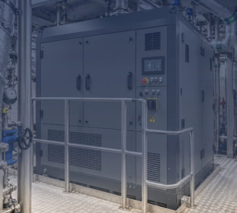
Waste heat recovery systems (WHRS) based on the Organic Rankine Cycle (ORC) convert available heat from sources such as exhaust gases and engine cooling water into electricity for use on board.
When this electricity displaces electricity from fuel-burning generating sets, fuel consumption and the associated CO2 emissions may decrease. Maritime ORC projects and studies show that, in suitable applications, fuel savings of around 5–10% are possible.
Actual net fuel savings depend on the available heat supply, engine load and operating hours, cooling conditions, the system’s own energy consumption and how much of the generated electricity can be used on board.
The ORC uses an organic working fluid that evaporates in a closed loop. The vapour expands in an expander that drives a generator. The installation links the heat source to the ORC module, cooling system and the ship’s electrical systems.
Module size and system configuration are matched to the vessel’s actual operating profile and the available installation space.
How the ORC Cycle Generates Electricity
In the evaporator, waste heat is transferred through a heat exchanger to the organic working fluid. The liquid evaporates and flows as vapour to an expansion machine, or expander. The vapour expands in the expander, driving a generator. Heat is then rejected in the condenser, causing the working fluid to condense back into a liquid. A pump raises the pressure of the liquid again and returns it to the evaporator.
The working fluid remains within the closed ORC cycle, separate from the heat source and cooling water. The properties of the fluid, expander and heat exchangers together determine the installation’s operating range. ORC can therefore also use heat at temperatures for which a conventional steam cycle is less practical. How much electricity the installation can produce depends in part on the temperatures on the hot and cold sides.
Which Waste Heat Is Actually Available?
For each heat source, temperature, flow rate and available heat are assessed in relation to engine load and operating hours. Exhaust gases, engine cooling water and available water, thermal-oil or steam circuits have different heat-transfer requirements. Depending on the design, the heat source is connected directly to the ORC installation’s heat exchangers or coupled through a separate intermediate circuit.
The heat balance shows what proportion of engine heat is available for electricity production. Existing heat demand for heating, hot-water production and other processes is considered separately. The share allocated to the ORC is determined by the remaining usable heat and the permitted reduction in heat-source temperature. Heat is then allocated between the different uses according to the actual supply.
Annual electricity output depends on heat-source temperature, the amount of heat available and how long it remains available. A lower-temperature heat stream available for long periods may allow more electricity to be generated than a hotter stream available only briefly. The calculation uses the performance of the selected ORC design and the cooling conditions during those periods.
When Is ORC Waste Heat Recovery Worth Investigating?
ORC may be particularly attractive when engines provide a usable and reasonably predictable supply of waste heat over a sufficient number of operating hours. A high exhaust gas temperature alone is not enough to establish this. The heat-source temperature, the rate at which heat is supplied and the hours for which those conditions hold, determine how much electricity can be generated in actual operation.
Electrical demand on board also provides an initial indication. Electricity from the ORC offers the greatest direct benefit when it reduces the output required from generating sets. The assessment therefore identifies when sufficient waste heat and electrical demand coincide during the vessel’s operating profile.
Available cooling also limits electricity generation. The ORC must be able to reject the remaining process heat through the condenser. Cooling-water temperature, flow rate and available cooling capacity therefore affect how much electricity can be produced from a heat source. Even when ample waste heat is available, cooling-side constraints may limit how much can be used.
In a retrofit, the practicalities of fitting the equipment on board also matter. Suitable locations must be found for heat exchangers, ORC modules, pipework, cooling equipment and electrical connections within the existing vessel. The distance from the heat sources, available engine-room space and possible pipe routes affect the project’s scope. In newbuild projects, this equipment can be incorporated into the energy-system design and engine-room layout at an earlier stage.
ORC may therefore be relevant to a range of applications in ocean-going, coastal and inland shipping. Examples include passenger ships, ferries, dredgers and offshore vessels with main or auxiliary engines running for long periods. However, ship type alone is not decisive. Usable waste heat, operating hours, cooling capacity and electrical demand determine the application’s potential.
An initial assessment therefore brings together engine load and operating hours, heat-source temperatures and flow rates, existing heat users, cooling conditions and the onboard electrical load. This helps establish at an early stage whether sufficient waste heat can be converted into usable electricity and whether more detailed technical and economic work on an ORC installation is worthwhile.
Extracting Heat Within Engine and Exhaust Gas Limits
When recovering heat from exhaust gases, the position of the additional heat exchanger and the amount of heat extracted are matched to the engine and existing exhaust system. The pressure drop across the heat exchanger adds to total exhaust gas back pressure and may affect engine fuel consumption. The total back pressure is therefore checked against the engine’s limits, and its effect is included in the calculation of net fuel savings.
The extent to which exhaust gases may be cooled depends in part on the fuel, material selection and any installed exhaust gas treatment equipment. When using engine cooling water, the required engine temperatures and flow rates, together with the existing temperature-control arrangements, govern the integration. Heat transfer to the ORC must be compatible with these requirements so that the engine retains its required cooling and temperature control.
When different heat sources are combined, their temperatures and flow rates are assessed for each operating mode. As engine load changes, the heat available from the exhaust gases and cooling water may respond differently. The heat exchangers, intermediate circuits and control arrangements are matched to these differences.
Matching Module Size and Number to the Operating Profile
Selecting the module size starts with the heat available and usable at the actual engine load. For each quoted power figure, the corresponding thermal input power, heat-source temperatures and cooling conditions must be clear. It is also recorded whether the stated electrical power is gross or whether certain auxiliary loads have already been deducted.
Where several engines are installed, it is important to establish which run simultaneously and at what loads. On that basis, a larger module or a combination of modules can be considered. The distribution of heat sources, pipe routes, available space and electrical demand determine which configuration is suitable. Combined electricity production is calculated for operating modes in which the necessary heat and cooling are available while there is sufficient electrical demand.
Part-load behaviour also matters in module selection. Smaller and larger designs are compared on the basis of the usable electricity they can deliver over the actual operating profile. The comparison also accounts for relevant engine loads, start-up periods and periods when insufficient heat is available for useful electricity generation.
Fuel Choice and Changes to the Engine Installation
An ORC uses heat released during engine operation and converts it into electricity through a separate cycle. Waste heat recovery can therefore be investigated for different engine and fuel configurations, including engines running on marine gas oil, heavy fuel oil, LNG, GTL, biofuels or methanol, as well as dual-fuel engines.
The fuel used affects exhaust gas conditions, heat distribution and heat exchanger requirements. For each application, temperatures and flow rates are therefore established for the operating modes in which the installation must function. These data provide the basis for matching the heat source and ORC design.
If the fuel changes, an engine is replaced or the ship’s operating profile changes, the heat balance, control system and expected electricity production must be reassessed. The reassessment establishes what electricity output is possible under the new conditions and whether the existing ORC design needs modification.
Assessing Cooling Capacity for the Condenser
After expansion, the condenser rejects the remaining heat so that the working fluid becomes liquid again. Cooling-water temperature and the available flow rate affect the condensing conditions and thus the ORC’s electrical power output. Warmer cooling water may limit production even when sufficient heat remains available on the hot side.
When connecting to an existing cooling circuit, the demands of other equipment using that circuit must also be considered. The pumps, central coolers and pipework must be able to handle the combined load under the relevant operating and ambient conditions. Recovering heat from engine cooling water may also change the distribution of heat load between cooling circuits. The heat-load distribution is therefore calculated for the entire installation.
For a representative output forecast, the heat supply and cooling conditions are combined for each operating mode. The calculation therefore uses the available heat and cooling-water temperatures present at the same time during actual operation.
Matching Electricity Production to the Shipboard Electrical System
The electrical connection must be compatible with the voltage, frequency, protection systems and control arrangements of the shipboard electrical system. The assessment also establishes how the ORC operates alongside generating sets and any battery storage, hybrid systems or other energy sources. Expected production is matched to the electricity that the ship can actually use during the relevant operating modes.
Electricity from the ORC can reduce the load on generating sets. Whether a generating set can be shut down altogether depends on the reserve required, the permitted engine load and the ship’s operating strategy. The assessment also establishes how output can be limited or the installation shut down safely when electrical demand is low.
When the ORC recovers heat from the same generating sets whose loads are reduced by its electricity output, the amount of waste heat available also changes. The resulting generating-set loads are therefore used in calculating the available heat. Expected ORC electricity generation is then based on the heat available at the resulting operating points of the generating sets.
Control and Safety During Normal Operation and Standstill
The control system coordinates the heat supply, circulation of the working fluid, expansion and cooling. During start-up, load changes and shutdown, both the ORC and the connected engine and cooling systems must remain within their operating limits. It must also be established in advance how the installation responds safely to the loss of cooling, electrical load or other essential services.
The original engine and cooling functions must remain available when the ORC is out of service. The necessary bypasses, valves and control arrangements are therefore specified to suit the installation. The precise arrangements depend on the selected heat source, intermediate circuit and connections to the existing shipboard systems.
Working fluid selection must take account of factors including operating pressure, temperature, flammability, toxicity and environmental properties. The properties of the selected fluid determine what measures are needed to manage leaks, provide ventilation, protect against pressure hazards and ensure safe handling. The safety concept is then developed for the actual ORC design and its location on board.
Integration and Maintenance in Retrofits and Newbuilds
Integrating the system involves more than finding space for the ORC module. Heat exchangers, pumps, pipework and electrical equipment must also be suitably located, with sufficient access for maintenance. The module’s location is therefore chosen to suit the heat sources, cooling system and electrical connections.
In a retrofit, the existing ship structure, available spaces and installed systems provide the starting point. Equipment dimensions and weight, access to the installation space and routes for pipework and cabling determine which work is required. Foundation work, installation and connections are planned around the available shipyard period. In a newbuild, these provisions can be developed earlier alongside the other shipboard systems.
Selecting a marine configuration also requires consideration of vibration, vessel motions, ambient temperature and foundation loads. The technical documentation must meet the applicable ship-specific, classification and flag State requirements. For any product or design approval, the configuration covered by that approval must be established. Integration on the particular ship also requires a separate assessment.
Heat exchangers must remain accessible for inspection and cleaning. Pumps, the expander, the generator, instrumentation and control equipment also require sufficient maintenance access. Heat exchanger fouling may affect both heat transfer and pressure drop. The maintenance plan is therefore matched to the heat source, working fluid and actual operating hours.
From Module Power to Net Annual Energy Output
To determine net electricity generation, it must be clear which components are included in the stated power output. The generator delivers electrical power, but working-fluid pumps, intermediate-circuit pumps, cooling equipment, controls and other auxiliary components may themselves consume energy. Their consumption is counted once in the energy balance. The assessment distinguishes auxiliary consumption already accounted for in the stated net power from additional consumption outside the module caused by the ORC.
It is then calculated how much of the net electricity generation can be used on board. Output for each operating mode is linked to the hours when sufficient heat and cooling coincide with sufficient electrical demand. Start-up, downtime, maintenance and any output restrictions are also taken into account. This uses power in kilowatts and the corresponding operating hours to estimate energy output in kilowatt-hours over the vessel’s operating profile.
Fuel savings depend on how much less energy the existing power generation system needs to supply because of the ORC. Fuel consumption is therefore calculated for the engines concerned at the resulting loads. Any additional losses, such as the effect of exhaust gas back pressure, are also included. This establishes the potential fuel savings from the net electricity generated for the ship as a whole.
The expected CO2 reduction is then linked to the calculated difference in fuel consumption and the fuel types used. The cases with and without the ORC are compared under equivalent operating conditions and for equivalent ship performance.
Substantiating Performance During Operation
For performance verification, measurement points and assessment conditions are established in advance. Temperatures and flow rates on the hot and cold sides are assessed in relation to electrical production, auxiliary consumption and operating status. Assessing these data over the same period establishes the conditions under which the measured power output was achieved.
A meter recording the ORC’s electrical output shows how much electricity it generates. To establish fuel savings, these measurements are assessed alongside the fuel consumption of the generating equipment whose load is reduced by the ORC. The assessment also accounts for changes in engine operation, electrical load and other shipboard systems.
The measurement method and its uncertainty are matched to the purpose of measurement, such as process monitoring, technical acceptance or contractual performance verification. Measured performance remains tied to the heat and cooling conditions under which it was established. For a complete annual forecast, the measurements are therefore supplemented by calculations for the other relevant operating modes.
Comparing Energy Output and Total Project Costs
The economic assessment starts with the net electricity that the ship can use during actual operation and the fuel or energy costs avoided as a result. The financial benefit also depends on the ship’s remaining service life, operating hours and the performance of the existing power generation system.
The investment includes more than the ORC module alone. Heat exchangers, pipework, pumps, electrical equipment, engineering, installation and any modifications to the cooling system or the ship’s structure also incur costs. Maintenance, working-fluid management and additional shipyard time are included as well. For a retrofit, a distinction is made between additional ORC costs and maintenance or replacement that would also be required without the project.
The sensitivity of the economic case is assessed using scenarios for heat supply, electrical demand, availability and energy prices. If the remaining heat supply is limited, the cooling system requires substantial expansion or electrical demand is low, a smaller ORC configuration or an alternative use of the heat may be more suitable. The assessment thus supports the decision to develop the ORC configuration under consideration further or pursue another approach better suited to the available waste heat.
ORC Performance Under EEDI, EEXI and CII
For ships to which these indices apply, electricity production from waste heat may be included in the Energy Efficiency Design Index (EEDI) or Energy Efficiency Existing Ship Index (EEXI). The applicable IMO methodology determines which electrical output and auxiliary consumption to use under the prescribed reference conditions. The contribution to the index is substantiated using data on the selected ORC configuration, its connected heat sources and the relevant verification.
For the Carbon Intensity Indicator (CII), actual annual operational performance matters. When the ORC reduces fuel consumption in service, this may contribute to lower operational CO2 intensity and a more favourable CII. The final CII and rating are determined from the complete annual data, prescribed ship capacity, distance travelled and applicable calculation rules.
Energy Investment Allowance for an ORC Installation
The Energy Investment Allowance (EIA) may be relevant to an investment in an ORC installation. Under this scheme, investments in energy-efficient business assets and technologies for using waste heat may, subject to conditions, qualify for an additional tax deduction.
Whether a specific ORC installation and the associated investment costs fall within the scheme is checked for each project against the current Energy List and applicable conditions. The timing of the investment commitment also matters for the application. It is therefore advisable to check the current eligibility and application requirements with the Netherlands Enterprise Agency (RVO) in good time and, where necessary, consult a tax adviser.
Practical Experience with ORC Waste Heat Recovery
Since 2016, we have supported the application of ORC-based waste heat recovery in shipping. Our experience includes retrofits and newbuild projects involving inland vessels, passenger ships, coastal vessels and specialist offshore vessels.
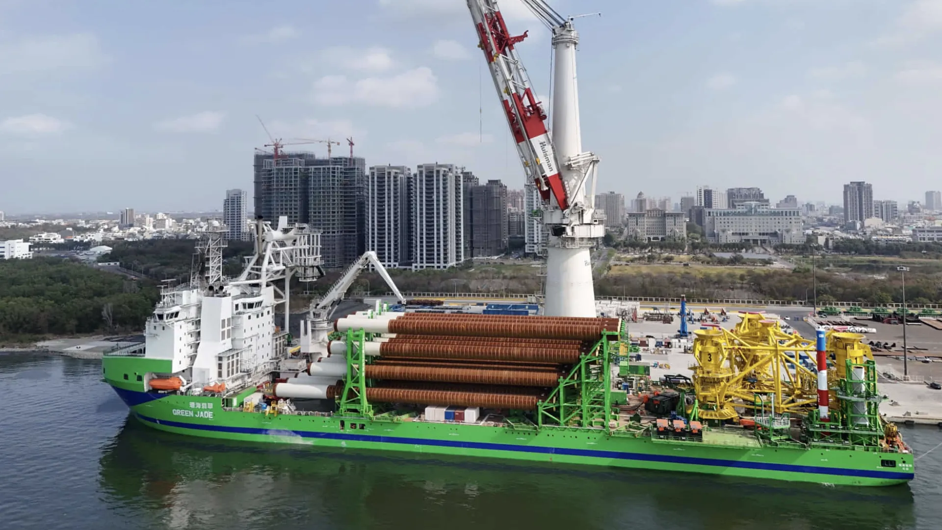
A practical example is the Green Jade. This wind turbine installation vessel has several engines and eight ORC modules. The installation uses heat from exhaust gases and engine cooling water to generate electricity on board.
Approach to Selecting and Implementing an ORC Installation
The initial project phase focuses on the available heat sources and the ORC configuration suited to them. The process configuration and expected electricity output are assessed alongside the available cooling and electrical demand. The assessment also identifies which existing arrangements can be retained and where connections or modifications are needed.
For the selected design, the heat exchangers, module configuration, cooling, electrical connection and control are developed in more detail. The technical proposal identifies the components and work included, the conditions under which the stated performance applies, and any additional data or assessments required. Expected energy output and project costs are based on the same configuration.
Once a decision is made to proceed with the project, further engineering and preparations for work on board begin. Documentation, approvals and the work itself are coordinated with the vessel’s requirements and the shipyard schedule. During commissioning, heat transfer, cooling, the electrical connection, control and agreed safety functions are checked. When performance verification is part of the project, measurement conditions and acceptance arrangements are established in advance.
Contact About an ORC Configuration for Your Ship
Would you like to assess which sources of waste heat on board could be used to generate electricity? We would be pleased to discuss which ORC configuration may suit your engine installation and operating profile. For a technical assessment, we would welcome details of the engines, fuels used, loads and operating hours, together with temperatures and flow rates for the available heat sources.
Information on existing heat demand, cooling-water temperatures, cooling capacity and electrical load helps determine the usable output. It is also important to know which generating sets operate in each mode and what power and fuel-consumption data are available for them. Please include this information in your enquiry wherever possible. A general arrangement plan and diagrams of the heat, cooling and electrical systems also help assess the connections required.
For a retrofit, the available installation space, pipe routes, planned shipyard period and intended changes to the engine or energy systems are relevant. For a newbuild, the available design can provide the basis. During our project discussion, we agree on any further information needed and how the technical work can be aligned with the schedule for your vessel.
Practical Experience with ORC Waste Heat Recovery
Since 2016, we have supported the application of ORC-based waste heat recovery in shipping. Our experience includes retrofits and newbuild projects involving inland vessels, passenger ships, coastal vessels and specialist offshore vessels.
A practical example is the Green Jade. This wind turbine installation vessel has several engines and eight ORC modules. The installation uses heat from exhaust gases and engine cooling water to generate electricity on board.