

When Does It Make Technical Sense to Combine Multiple Energy Saving Devices (ESDs)?
Author: Jeroen Berger • Publication date:
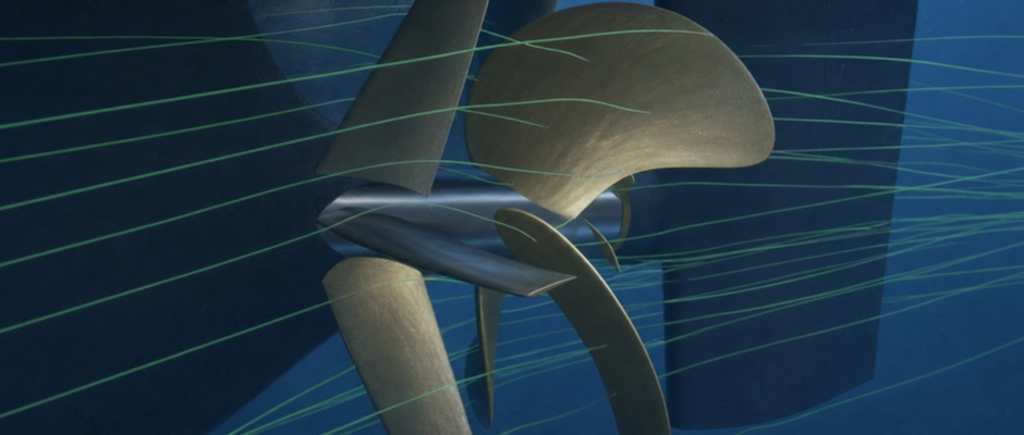
A combination of multiple Energy Saving Devices (ESDs) makes technical sense when the devices together save more propulsion power than the best individual solution and the additional technical complexity is justified. A Pre-Swirl Stator (PSS) or Pre-Duct can improve propeller inflow, while Propeller Boss Cap Fins (PBCF) or a Rudder Bulb influences the flow around the propeller hub and rudder. This offers opportunities to reduce different hydrodynamic losses, but the devices do not operate independently of one another. A change in propeller inflow also affects propeller loading and the flow that reaches components behind it. ESDs may therefore reinforce one another, partly reduce the same loss or adversely affect each other’s performance. The individual savings must therefore not simply be added together. Whether a combination is suitable depends on the additional power saving, the hydrodynamic interaction between the devices and the possibilities for integrating them safely and reliably into the existing or planned propulsion system.
When Do Different ESDs Complement Each Other Hydrodynamically?
ESDs can complement one another when a first device reduces hydrodynamic losses and a second device can offer improvement in an area that remains afterwards. This may be the case, for example, when inflow ahead of the propeller is improved while losses around the hub or in the interaction with the rudder remain behind the propeller. The location of the two devices gives an initial indication, but does not independently determine whether their effects complement one another.
A Pre-Swirl Stator, for example, changes the direction in which the water reaches the propeller. The relative inflow angles and loading of the propeller blades may change as a result. Rotation in the propeller slipstream and flow towards the rudder may also shift. If a Rudder Bulb is used behind the same propeller, the bulb must therefore be matched to the flow that develops with the stator present. The originally favourable bulb geometry need not remain the best design under these conditions.
A similar interaction develops between a Pre-Duct and a PBCF. The duct influences the speed and direction of the water ahead of the propeller plane. The propeller may consequently be loaded differently, and the hub flow on which the PBCF acts may also change. A PBCF designed for the original propeller performance may make a different hydrodynamic contribution after the duct is added. In time-dependent flow calculations for this combination, both more favourable axial flow and less rotation-related energy around the hub have been found. These local flow results do not yet describe overall propulsion efficiency. Whether they also yield an additional reduction in required shaft power must be established for the complete propulsion system.
It is therefore insufficient to establish that two ESDs have different operating principles. The first device may materially change the conditions for which the second was designed. A more favourable interaction sometimes develops as a result, but it may also mean that less improvement remains for the second device. The additional contribution becomes apparent only when both components are assessed together with the propeller and rudder.
Which ESD Combinations May Be Technically Promising?
A Pre-Swirl Stator combined with a Rudder Bulb is an example of two devices operating on opposite sides of the propeller. The stator changes the inflow direction, while the bulb influences the flow between the propeller hub and rudder. For a large ore-carrier model, self-propulsion trials at sea and numerical calculations were used to compare the combination with the configuration without either device. Improved propulsion performance was reported for that comparison. The technical possibility is thus substantiated, but not the proposition that every propeller–rudder arrangement performs better with both devices than with the individual ESDs. The additional value must be established for the configuration concerned.
A Pre-Duct and Pre-Swirl Stator can also be combined. The duct influences flow guidance towards the propeller plane, and the stator fins generate controlled pre-swirl. These functions can be brought together in an integrated structure, for example with fins inside a duct. The duct profile then influences the inflow to the fins, which in turn change the flow towards the propeller.
Such an integrated design must be developed as a whole. The most favourable duct shape without stator fins need not remain the same when the fins are added. Their position, profile shape and setting angle may also change because both components act on the same flow. In a fully integrated design, the individual contributions cannot always be distinguished without additional comparisons either. A combined duct–stator device is therefore more than simply joining two existing designs.
A Pre-Swirl Stator and a PBCF can also complement one another. The stator changes the inflow ahead of the propeller, while the PBCF influences the flow around the rotating boss cap. Numerical open-water calculations for such a combination show an improvement over the baseline propeller without either device. The separate additional benefit over a stator alone was not established in that comparison. The results of the investigation depend on the specific propeller, stator geometry and hub fins, however. Changes in thrust, torque or propeller efficiency must not be directly equated with the fuel saving of a complete ship.
For a PBCF and Rudder Bulb, the considerations differ. Both devices can reduce losses around the propeller hub, but act from different components. The PBCF rotates with the boss cap and influences the flow immediately behind the propeller blades. The Rudder Bulb forms part of the rudder and influences the transition between the propeller hub and rudder. Their hydrodynamic contributions may therefore partly overlap without being identical.
If a Rudder Bulb already strongly influences the hub vortex, the additional contribution of a PBCF may become smaller. This does not rule out further improvement. The hub fins can still generate favourable hydrodynamic forces and influence the flow differently from the bulb. For certain seagoing ships, special PBCF designs have therefore been developed that can also be used with limited distance to a Rudder Bulb. The availability of such a design does not, however, prove on its own how much additional shaft power the ship concerned saves.
The technical significance of these combinations therefore differs between configurations. For a Pre-Swirl Stator and Rudder Bulb, the potential for complementary effects lies mainly in the modified flow ahead of and behind the propeller. An integrated Pre-Duct with stator fins calls for joint optimization of components that influence the same inflow. For a PBCF and Rudder Bulb, the partly overlapping effects around the hub and the available installation space warrant particular attention. Which combination is preferable follows from their combined performance, rather than a fixed ranking of ESD types.
When Can ESDs Work Against Each Other?
Two individually effective ESDs may together save less power than the sum of their individual improvements. There are different explanations for this, which must be distinguished in a technical assessment.
One possibility is overlapping effects. If a Pre-Swirl Stator changes the flow so that certain losses behind the propeller are already smaller, less scope for improvement may remain for a device behind it. The second ESD may then still contribute positively, but less than if it were used alone on the original ship. This is not necessarily a negative hydrodynamic interaction: part of the original loss has simply already been reduced.
A second possibility is that the devices actually affect each other’s performance adversely. In a Pre-Duct with stator fins, for example, a flow distribution may develop for which the selected fin settings are not sufficiently well suited. The fins may then cause additional losses, while the resulting inflow is less favourably matched to the propeller blades. Modified duct or stator geometry may be needed to improve their interaction.
Unfavourable effects may also occur behind the propeller. A PBCF can reduce the hub vortex, but simultaneously changes the flow and pressure distribution that reach the rudder. Research on PBCFs in propeller–rudder arrangements shows that favourable performance around the hub can coexist with higher rudder drag. The net improvement in the complete propulsion system may therefore be smaller than the improvement in the propeller alone.
A third possibility is that the individual designs are not optimal in combination. A stator that generates favourable pre-swirl without a Rudder Bulb need not retain the same geometry when the bulb is added. The same applies to a PBCF that encounters a different hub flow in combination with a Pre-Duct. Joint optimization may then produce a better result than combining two separately designed devices without modification.
Combinations can also change the pressure distribution and fluctuating loads on the propeller and rudder. Possible effects on cavitation, vibration and manoeuvrability must therefore be investigated. Lower average power demand is not sufficient if the combined configuration causes technically unacceptable effects under necessary operating conditions.
The distinction between overlapping effects, genuinely adverse interaction and insufficient joint optimization is important. A disappointing saving shows that the combination delivers less benefit than expected, but does not yet explain which hydrodynamic mechanism is responsible. Even when the combined saving is smaller than the sum of the individual savings, the combination may still outperform each individual device.
Which Structural Constraints Determine Whether a Combination Is Feasible?
A hydrodynamically promising combination must fit within the existing or planned ship configuration. Particularly around the propeller plane, the available space, attachment points and distances between components can limit the feasible geometry.
For a Pre-Duct and Pre-Swirl Stator, sufficient space must be available for the duct, stator fins and any supporting structures. When the two functions are integrated, components can share attachments. This can offer structural advantages, but also changes the distribution of hydrodynamic forces. The strength and stiffness of the support must therefore be assessed for the complete configuration.
The attachment structure must also accommodate the fluctuating loads that may occur during operation. A device that performs favourably when sailing straight ahead may experience different forces under other propeller loads or manoeuvring conditions. Susceptibility to vibration and maintenance access are also relevant. The necessary support must not disturb the flow to the propeller to such an extent that the expected hydrodynamic improvement is substantially lost.
Behind the propeller, the boss cap, propeller–rudder distance and existing rudder geometry are particularly decisive. A PBCF requires space for the hub fins and a suitable attachment to the rotating boss cap. A Rudder Bulb must suit the geometry of the propeller hub and maintain sufficient clearance from rotating parts. When the devices are combined, the available distance can severely limit the feasible shapes.
A shorter PBCF can offer a solution in certain configurations, but reducing the boss cap length or modifying the fins also changes the hydrodynamic effect. A structurally suitable design is therefore not automatically an efficient one. The modified geometry must be reassessed for its contribution to the complete propeller–rudder arrangement.
Additional constraints may apply to a Controllable Pitch Propeller (CPP). Not every controllable pitch hub is suitable for a PBCF. The boss cap design, attachment options and any space required for movement of the adjustable blades must suit the chosen design. Where a Rudder Bulb is also present, the relevant clearances and operating positions must be checked.
The options also differ between newbuild and retrofit. For a newbuild, distances between components, attachment points and maintenance access can be considered from the outset. On an existing seagoing ship, the available space and structure are largely fixed. A combination that is attractive for a newbuild may therefore require extensive modifications in a retrofit or prove less suitable technically.
Ultimately, feasibility therefore depends on more than whether both devices can be installed individually. Their combined geometry, loads, space for movement and maintainability must fit within the complete propulsion configuration.
How Is the Additional Performance of Multiple ESDs Established?
The technical benefit of a combination is assessed by establishing the shaft power required by the complete propulsion configuration. The ship’s speed through the water, draught, trim and other relevant initial conditions are kept the same. Rotational speed and torque may differ between configurations, because changing how the propeller operates is precisely what an ESD does.
For two devices, a comparison of four configurations provides a clear basis: the ship without ESDs, with device A only, with device B only and with both devices together. This comparison shows how much the individual designs save and what result is obtained when they are combined.
A hypothetical example illustrates the difference. Suppose a coastal vessel requires 4.000 kW of shaft power at a certain speed without an ESD. With device A only, this falls to 3.880 kW, and with device B only to 3.920 kW. If the two devices together require 3.850 kW, the combined saving is 150 kW.
Device A alone saves 120 kW and device B 80 kW. When B is added to the configuration with A, however, power falls from 3.880 to 3.850 kW. The additional contribution of B is then 30 kW. The individual savings of 120 and 80 kW must therefore not be added together to predict the combined result.
The reverse comparison is also relevant. When device A is added to the ship on which B is already present, power demand falls from 3.920 to 3.850 kW. The additional contribution of A is then 70 kW. The extra gain from each device therefore depends on the configuration used for comparison.
In this example, the combined saving is 50 kW below the sum of the two individual savings. Yet the combination saves more power than either individual device. The difference of 50 kW demonstrates that the effects are not additive, but does not prove that the two devices counteract each other hydrodynamically. To establish that, the flow and forces on the individual components must be investigated. The stated power values are solely hypothetical figures for calculation and do not constitute a prediction for a real ship.
The four configurations must also be compared on the same design basis. When A and B have been optimized individually and are then combined without modification, the comparison describes the interaction between those existing designs. If the geometry of both devices is subsequently adjusted jointly, a new configuration results. Its performance may be better or worse, but must be reported separately.
For a CPP, it must also be clear how the propeller settings are treated. If the most favourable combination of blade pitch and rotational speed changes after an ESD is added, this may form part of the overall propulsion improvement. The assumptions for the control strategy and the permitted optimization must then be equivalent for all configurations investigated.
Computational Fluid Dynamics (CFD) can provide insight into the changed inflow, pressure distribution and hydrodynamic forces. Particularly for combinations, propeller operation must be described with sufficient accuracy to assess the relevant interactions reliably. Model tests can further substantiate the calculated performance and help assess scale effects. Predicting the shaft power required at full scale calls for a suitable assessment and extrapolation method.
Where additional savings are small, uncertainty warrants particular attention. A predicted improvement from the second device has little value for decision-making if the difference cannot reliably be distinguished from the uncertainty in the calculations or measurements. The technical conclusion must therefore reflect the accuracy with which the additional contribution has actually been established.
When a seagoing ship operates at different speeds or in different loading conditions, the interaction between the ESDs may also change. A combination that performs favourably at the nominal cruising speed need not deliver the same additional saving at a different propeller loading. The technical assessment must therefore take the relevant operating conditions into account. A predicted shaft power saving must also not be equated with the same percentage fuel saving without further assessment.
When Is a Single ESD the Better Technical Solution?
A single ESD is preferable when it already reduces the main hydrodynamic losses sufficiently and a second device delivers little additional improvement. The extra structure may then introduce greater complexity, more maintenance and potential sources of faults or vibration without a meaningful power saving in return.
This can be particularly relevant to devices that partly influence the same flow around the hub. A PBCF and Rudder Bulb may each be promising, while the combined improvement remains limited because their effects partly overlap. A limited propeller–rudder distance may also mean that both designs have to be modified so extensively that the original hydrodynamic benefits are reduced.
The situation is different when, after the first device has been fitted, clear potential for improvement remains that a second ESD can effectively address. Particularly for a newbuild or an extensive retrofit, jointly developing the geometry can then deliver a worthwhile improvement. The combination must, however, be technically feasible and continue to function with sufficient reliability under the relevant operating conditions.
Where hydrodynamic performance is comparable, practical differences may also become decisive. A single device may be easier to attach, more accessible for inspection and require less extensive modification of the existing stern. A small predicted additional saving with uncertainty is then not necessarily a good reason for a more complex structure.
A combination of multiple Energy Saving Devices makes technical sense when the devices together deliver an additional power saving that is substantiated with sufficient reliability and their hydrodynamic and structural operation is well matched. The decisive question is not how many individual devices can be fitted, but what improvement the second ESD actually adds to the configuration already in place. If that benefit remains limited, is insufficiently certain or is accompanied by unacceptable technical disadvantages, a well-matched single device is the better solution.
This Article in the Series
Whether multiple devices complement each other also depends on matching ESDs to a fixed pitch propeller or CPP, where blade pitch, propeller loading and hub structure matter. Even when a combination is technically feasible, maintenance or reoptimization may be a better first step than an ESD. How these considerations relate to each other within the complete propulsion system is discussed in the configuration of ESDs in ship propulsion.