

How Does ESD Design Differ Between a Fixed Pitch Propeller (FPP) and a Controllable Pitch Propeller (CPP)?
Author: Jeroen Berger • Publication date:
The design of an Energy Saving Device (ESD) differs between a fixed pitch propeller and a Controllable Pitch Propeller (CPP) mainly because the blade pitch of a CPP can change during operation. On a fixed pitch propeller, the geometric blade pitch remains unchanged, while a CPP can deliver thrust at different pitch settings. The loading on the propeller blades and the flow around the propeller and hub change as a result. An ESD, whose geometry is generally fixed, must match these conditions hydrodynamically. This places additional demands on the matching of a Pre-Swirl Stator (PSS), Pre-Duct, Propeller Boss Cap Fins (PBCF) or Rudder Bulb. The construction of the pitch adjustment mechanism also plays a role, particularly for devices around the propeller hub. Both propeller types can be combined with an ESD, but for a CPP the design must account for the relevant blade pitch settings, the corresponding rotational speeds and their influence on propulsion. The challenge is to enable the device to operate efficiently at the main operating settings while maintaining technical suitability within the required operating range.
What Changes in Propeller Geometry and Inflow?
On a Fixed Pitch Propeller (FPP), the blades have a fixed geometric orientation relative to the hub. Hydrodynamic loading can, however, change during operation. When the ratio between inflow speed and rotational speed shifts, the direction from which the water reaches the rotating blades changes. The hydrodynamic angle of attack, pressure distribution and forces on the blades change as a result, although the blade geometry remains the same.
On a CPP, the blades can rotate about their own pitch adjustment axes. The geometric blade pitch changes as a result, without the shape of each individual blade section changing. The hydrodynamic angle of attack is also determined by the relative inflow, which is related to rotational speed, ship speed and the flow induced by the propeller, among other factors. A change in blade pitch therefore does not necessarily lead to an equally large change in the hydrodynamic angle of attack. The distribution of blade loading, required torque and flow behind the propeller may nevertheless shift.
This distinction has direct consequences for an ESD. With an FPP, the device interacts with a fixed blade geometry that functions under different hydrodynamic loads. With a CPP, the geometric orientation of the blades can also change. Two operating settings at almost the same ship speed may therefore involve different combinations of blade pitch, rotational speed and propeller loading. The pre-swirl that a stator generates or the flow that a hub device influences need not make the same contribution to propulsion at those settings.
This does not mean that a CPP is less suitable for an ESD. Adjustability offers opportunities for favourable propeller performance under a range of conditions. For ESD design, it must simply be clear which settings are actually used and how the device responds to them. For an FPP, assessment across the relevant operating points is also needed, but there is no additional variation in geometric blade pitch during operation.
How Does the Matching of a Pre-Swirl Stator or Pre-Duct Differ?
A Pre-Swirl Stator (PSS) uses fixed fins ahead of the propeller to generate controlled pre-swirl in the opposite direction to propeller rotation. The device thereby changes the relative inflow to which the propeller blades respond. The shape and orientation of the stator fins are matched to the local flow and the way in which the propeller uses the pre-swirl generated.
For an FPP, this matching can be developed in conjunction with the fixed blade-angle distribution. The stator must then continue to interact favourably with the propeller at the relevant rotational speeds and loads. For a CPP, the influence of adjustable blade pitch is an additional factor. The stator fins retain the same geometry, but the relative inflow angles and loading of the propeller blades may change with the pitch setting. The distribution of pre-swirl that the propeller can use favourably may therefore also differ between operating settings.
For engineering, the main consideration is which combination of stator geometry and CPP settings in use reduces power demand. A stator that delivers a favourable improvement at a high blade pitch need not be equally effective at a lower blade pitch. The greatest pre-swirl at a single setting is also not necessarily the best design outcome. The stator itself produces hydrodynamic forces and losses, which must be assessed together with the changed propeller performance.
A Pre-Duct primarily influences flow guidance towards the propeller plane. The duct changes the local velocity distribution and flow direction, while the pressure distribution on the duct profile produces hydrodynamic forces of its own. The operating propeller also influences the flow and pressure distribution around the duct. For the net power improvement, therefore, both the modified inflow and the contribution of the duct itself matter.
With an FPP, this interaction changes when inflow, rotational speed and loading shift. With a CPP, blade pitch may additionally change propeller loading and the associated pressure field. The same duct may therefore have a different influence on inflow and overall propulsion performance at different pitch settings. For integrated duct designs with stator fins, the pre-swirl generated must also be included in the assessment.
The practical design question is similar for both devices: which fixed geometry delivers a favourable improvement under the main operating conditions? For a CPP, however, that question must also be answered for the relevant variation in blade pitch. This may mean that a stator or duct geometry with a slightly smaller improvement at the nominal setting is ultimately more suitable, because performance remains more favourable at other frequently used CPP settings.
Using a Pre-Swirl Stator or Pre-Duct with a CPP therefore does not require a different fundamental operating principle. The difference lies in hydrodynamic matching to a propeller whose geometric blade pitch can change during operation.
What Implications Does the CPP Hub Have for a PBCF or Rudder Bulb?
Around the propeller hub, the structural differences between an FPP and a CPP become more apparent. On a fixed pitch propeller, the blades are connected to the hub in a fixed orientation. A CPP contains a mechanism that allows the blades to rotate about their pitch adjustment axes. The blade feet, attachments and components of the hydraulic or mechanical pitch adjustment system therefore place specific demands on the hub structure. Depending on the design, the hub dimensions and boss cap shape may also differ from those of a comparable fixed pitch propeller.
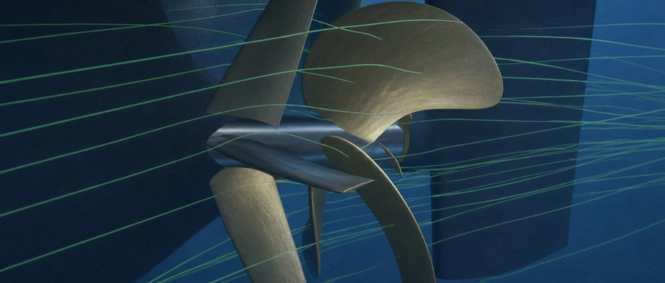
For Propeller Boss Cap Fins (PBCF), the combination of hub geometry and local flow is particularly important. The fins are installed on the rotating boss cap and influence the flow that develops behind the propeller blades and around the hub. On an FPP, the shape, orientation and position of the fins can be matched to the fixed blade geometry and the flow around the blade roots.
On a CPP, this flow changes when blade pitch is adjusted. The PBCF rotates with the hub, but the geometric orientation of the fins does not change along with the adjustable propeller blades. The hydrodynamic interaction between the blade roots, boss cap and fins may therefore differ at different pitch settings. The influence on the hub vortex, propeller torque and forces on the PBCF may consequently change.
In a numerical open-water study, a model of a controllable pitch propeller was compared with and without a PBCF at four pitch ratios. This setup investigates propeller performance at different blade pitch settings without reproducing the complete hull–propeller–rudder interaction. The results of this investigation, however, relate to specific propeller configurations and cannot be translated into the power saving of a complete ship without further assessment. For the design, it therefore remains important how the selected PBCF performs with the actual CPP hub and at the relevant operating settings.
Alongside hydrodynamic matching, the device must be structurally suitable. A PBCF can be used on certain CPP systems, but not every hub structure offers the same possibilities. The boss cap shape, attachment, existing parts of the pitch adjustment mechanism and any requirements of the propeller manufacturer may impose constraints. Depending on the design, it must also be checked whether the available space remains suitable when the propeller blades are adjusted. The complete hub structure and required pitch adjustment range are therefore more important than the nominal blade pitch alone.
For a Rudder Bulb, the difference is of another kind. The bulb forms part of the rudder and is matched to the flow between the propeller hub and rudder. For both an FPP and a CPP, the hub shape, propeller–rudder distance and relative alignment are important. The geometric fit must suit the actual components and available space.
A CPP may have a different hub shape from a comparable fixed pitch propeller. This may affect the feasible contour and position of the Rudder Bulb. A change in blade pitch may also influence the characteristics of the propeller slipstream. The bulb may therefore encounter a different velocity and pressure distribution at different pitch settings. The effect on the complete propeller–rudder arrangement must be assessed, because a favourable change around the hub does not automatically deliver an equally large net power improvement.
Adjustable blade pitch does not automatically make a Rudder Bulb more difficult to install. Structural suitability depends mainly on the hub and rudder geometry, while hydrodynamic matching is also determined by the flow that the propeller leaves behind at the relevant blade pitch settings.
The distinction between the two hub-related devices therefore remains important. A PBCF must directly suit the rotating boss cap and the flow around the propeller blades. A Rudder Bulb is matched, from its position on the rudder, to the geometry and flow in the region behind the propeller hub. With a CPP, both devices call for attention to changing propeller performance, but the structural consequences are not the same.
Which Blade Pitch Settings and Operating Conditions Determine the Design?
For ESD matching, it must be known under which conditions the propeller operates in service. For an FPP, these include the relevant combinations of inflow speed, rotational speed and loading. For a CPP, the blade pitch settings actually used and the associated control strategy are additional factors. In particular, the way in which blade pitch and rotational speed are controlled together determines which flow conditions the ESD encounters during normal operation.
A CPP on a coastal ship or RoRo ship may, for example, operate for long periods at an almost constant rotational speed, with the required thrust controlled mainly through blade pitch. In another installation, rotational speed and blade pitch may change together. Connected equipment, such as a shaft generator, may also influence the permitted rotational speed settings, depending on the electrical configuration. In these cases, the ESD must be matched to the operating settings that the propulsion installation actually uses.
This does not mean that every possible pitch setting must carry equal weight in optimization. In particular, the operating settings at which the propeller handles substantial propulsion energy over extended periods determine where an efficiency improvement has the greatest value. An ESD is therefore not automatically matched to the maximum blade pitch or solely to the nominal cruising speed. For a ship that operates almost continuously within a narrow pitch range, targeted optimization may be appropriate. When different blade pitch settings are frequently used in service, matching across a wider range warrants attention.
The control strategy itself may also become part of the design assessment. An ESD may change the relationship between required thrust, propeller rotational speed and torque. The most favourable combination of blade pitch and rotational speed with an ESD may therefore differ from the original setting without an ESD. Whether that change can actually be used depends on the available control options and the operating limits of the propulsion installation.
Alongside hydrodynamic optimization, there is a separate requirement for technical suitability. During manoeuvring, astern operation and other necessary operating settings, blade pitch, thrust direction and flow may differ substantially from normal ahead operation. A CPP can deliver astern thrust by reversing blade pitch without the direction of propeller shaft rotation needing to change. The ESD need not deliver the same efficiency gain in these situations, but must be suitable for the loads and flow conditions that may occur. The required steering and manoeuvring performance must also be maintained.
For a CPP, two design questions must therefore be answered separately. At which blade pitch settings and rotational speeds must the ESD actually save energy? And under which other operating settings must the device continue to function safely and reliably? This distinction prevents a favourable result at a nominal blade pitch from incorrectly being regarded as evidence of the suitability of the entire installation.
How Is ESD Design Assessed for the Two Propeller Types?
The design assessment starts with the geometry and operating data of the existing or planned propeller. For an FPP, the diameter, blade geometry, hub shape, direction of rotation and relevant rotational speeds and loads are needed, among other data. For a CPP, the blade pitch settings used, corresponding rotational speeds and data on the adjustable hub must also be available.
Additional geometric information is important for devices around the hub. A PBCF must fit the actual boss cap and attachment possibilities. For a CPP, data on the blade feet, pitch adjustment mechanism and space for movement may be necessary to establish structural suitability. For a Rudder Bulb, the hub shape, propeller–rudder distance and rudder geometry are particularly relevant.
How the ESD interacts with the propeller at the selected operating settings is then investigated. Hydrodynamic calculations can show how the local inflow, propeller loading and forces on the device change. For a CPP, the influence of the relevant blade pitch settings must be described with sufficient accuracy. Particularly for a PBCF, the local flow around the blade roots and hub may require detailed propeller modelling. Model tests can provide additional substantiation, with the prediction of full-scale performance requiring separate attention.
A useful comparison starts from a clear reference without an ESD. The same ship speed, draught, trim and relevant environmental conditions are maintained for the reference and the proposed design. The required rotational speed and torque may differ, precisely because the ESD can change propeller performance. The comparison must cover the complete propulsion system, including the hydrodynamic forces on the hull, propeller, rudder and ESD.
For a CPP, it must also be clear how the control strategy is treated. If one configuration is assessed with an optimized combination of blade pitch and rotational speed while the other retains the original settings, the calculated difference cannot automatically be attributed solely to the ESD. For a fair comparison, it must therefore be established which operating settings are permitted for both configurations and whether any control adjustments form part of the proposed solution. A distinction thus remains possible between the effect of the ESD and an improvement resulting from different propeller control.
A more favourable inflow angle, a smaller hub vortex or higher propeller thrust at the same rotational speed is insufficient evidence of energy saving on its own. The relevant measure is how much shaft power the ship requires for the same performance. The assessment must also account for the uncertainty of the calculations or model tests used. A predicted power reduction cannot, moreover, be equated with the same percentage fuel saving without further analysis.
The hydrodynamically promising design must then be checked structurally. For an FPP, the emphasis is on attachment, available installation space and matching to the existing propeller and rudder arrangement. For a CPP, the hub structure, adjustable blades and required space for movement may impose additional requirements. Cavitation, vibration, loads under different operating settings and manoeuvrability must also remain technically acceptable throughout the required operating range.
The fundamental operating principle of an Energy Saving Device does not change because a ship has a fixed pitch or controllable pitch propeller. With an FPP, the ESD interacts with a fixed blade geometry under varying hydrodynamic loads. With a CPP, variation in geometric blade pitch is an additional factor, with consequences for propeller flow, possible matching of the control strategy and sometimes structural integration. A suitable design accounts for these differences and delivers a reduction in power demand, substantiated with sufficient reliability, at the main operating settings without losing technical suitability under other necessary operating conditions.
This Article Within the Series
Alongside the propeller design, the ship’s operational profile also determines which operating conditions are important for matching an ESD. Devices that perform favourably individually do not automatically offer extra benefit together. This calls for an assessment of the technical suitability of combined ESDs. These design considerations form part of the broader matching of ESDs to ship propulsion.