

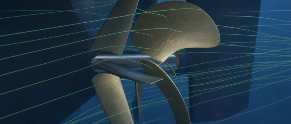
Ship Propulsion and Configuration of Energy Saving Devices (ESDs)
An Energy Saving Device (ESD) can reduce a ship's power demand by improving the flow around the propeller. A suitable design can thus reduce fuel consumption and the associated CO2 emissions. Which device is suitable depends on the stern, propeller, rudder arrangement and how the ship is used. Selection starts by identifying where further improvement is possible: in the technical condition, the matching of the existing propulsion system or the flow ahead of and behind the propeller. This distinction guides the choice of an individual ESD or a combination, and determines which components need to be developed together.
First Establish Where Propulsion Can Be Improved
A gradual deterioration in propulsion performance calls for a different approach from a propeller that is no longer well matched to current service. Where there is fouling or propeller damage, maintenance can help restore previous performance. Where there has been a lasting change in the operational profile, a different propeller geometry or propulsion control may be more suitable. The cause determines when maintenance or reoptimization should take priority over an ESD. An ESD influences the flow around the propulsion system, but does not replace the repair of damaged propeller blades or an assessment of propeller matching.
Even a well-maintained and appropriately matched propulsion system may have remaining losses that an ESD can specifically address. Maintenance and propeller optimization do not have to be completed before these possibilities are investigated. Where propeller replacement is already planned, the new propeller and, for example, a stator can be developed together. Selection then takes the intended final configuration as its basis, with separate expectations for the restoration of performance and the additional hydrodynamic improvement.
Hull–Propeller–Rudder Interaction as the Basis for ESD Selection
The water behind the hull does not reach every part of the propeller at the same speed and in the same direction. This wake field affects blade loading. The propeller then changes the flow towards the rudder, while the rudder also influences the flow and pressure at the propeller. This interaction explains how hull–propeller–rudder interaction determines ESD suitability. A favourable local change in flow must also be compatible with the operation of the other components.
A non-uniform wake field calls for a different design investigation from losses around the boss cap. In both cases, what matters is the shaft power required by the complete configuration at the same speed through the water and under equivalent ship and environmental conditions. The forces and losses associated with the added device also form part of that comparison. A local flow improvement therefore indicates a promising design; it does not, on its own, demonstrate improved ship performance.
ESD Solutions Ahead of and Behind the Propeller
Ahead of the propeller, a Pre-Swirl Stator (PSS) uses fixed fins to generate controlled pre-swirl in the opposite direction to propeller rotation. This changes the relative inflow to the propeller blades. A Pre-Duct uses a profiled duct to influence the speed and direction of the water reaching the propeller plane. This duct is positioned ahead of the propeller, unlike a nozzle that surrounds the propeller.
The operating principles overlap to some extent. Stator fins can also influence the axial inflow, and a duct may contain fins that generate pre-swirl. The desired flow adjustment, available space and mounting options determine which geometry is investigated further. Where installation at the hydrodynamically preferred position is not feasible, a modified geometry or a different device may be considered.
Behind the propeller, Propeller Boss Cap Fins (PBCF) influence the flow around the hub with fins on the rotating boss cap. The fins change the development of the hub vortex and the forces acting on the propeller with its cap and fins. A Rudder Bulb is attached to the rudder and influences the flow between the propeller hub and the rudder. For the PBCF, matching to the propeller and connection to the boss cap are central considerations. For the bulb, alignment relative to the hub and connection to the rudder are also determining factors.
Clearance from rotating propeller components limits the feasible shapes and dimensions. For a bulb on the moving rudder blade, clearance at the relevant rudder angles also matters. The choice between a Pre-Swirl Stator, Pre-Duct, PBCF or Rudder Bulb thus links the identified flow loss to the possibilities offered by the specific propeller–rudder arrangement.
Fixed Pitch Propellers and CPPs Require the Design to Be Matched Differently
With a Fixed Pitch Propeller (FPP), the geometric blade pitch remains unchanged. The hydrodynamic loading does, however, vary with inflow and rotational speed. With a Controllable Pitch Propeller (CPP), the blade pitch can also change. The same ship speed can therefore be associated with different combinations of blade pitch and rotational speed, with different flow around the blades and hub.
The settings used and the hub construction explain the difference between ESD design for a fixed pitch propeller and for a CPP. A PBCF must suit the specific boss cap, mounting arrangement and clearance for the adjustable blades. For a Rudder Bulb, the hub shape, rudder geometry and distance between them remain important. A CPP does not rule out the use of an ESD; the assessment must reflect the actual propeller design and the way it is controlled.
The Operational Profile Determines Which Improvement Is Valuable
Even with the same propeller, the ship may operate under widely varying conditions. Laden and ballast conditions, as well as differences in speed and trim, change the inflow and required thrust. The effect of the operational profile on an ESD's performance may therefore change the preference for a particular geometry.
The focus when matching the design is on the conditions in which the ship actually uses propulsion energy. Both power demand and the hours spent at each operating point matter. A high percentage saving at a rarely used operating setting need not make the greatest contribution in service. Anticipated changes in speed or loading are therefore taken into account during selection.
The device must also remain suitable for necessary operating settings outside the main operating range. During manoeuvring, the saving need not be the same as during normal ahead operation, but loads and steering performance must remain acceptable. Cavitation and vibration require attention under the conditions in which these phenomena are relevant.
A Single ESD or a Combination of Devices
Several devices can reduce different losses, but also affect one another's operation. A stator, for example, changes the flow reaching a Rudder Bulb behind it. The bulb must be matched to that altered inflow. A PBCF and Rudder Bulb may also reduce some of the same hub losses. A combined saving below the sum of the individual savings therefore does not automatically mean that the devices work against each other: part of the loss may already have been reduced by the first device.
A comparison with the best individual solution reveals the additional technical benefit of multiple ESDs within the same configuration. Comparison only with the ship without ESDs is insufficient for this purpose. The magnitude and reliability of the additional power saving are weighed against the additional structure, space requirements and maintenance needs.
From a Promising Configuration to Further Development
The initial project discussion focuses on which propulsion components will be retained and which modifications are being considered. Drawings of the aftship, propeller and rudder, and data on speed, power and operating conditions guide that choice. Together with a specialist international partner, we support the assessment of promising ESD designs and their interaction with any proposed propeller or rudder modifications.
The selected configurations provide the starting point for Hydrodynamic Design and Performance Validation of Energy Saving Devices (ESDs) for Ships. That investigation must substantiate the power benefit that the selected design can provide under representative conditions. Further structural development and the assessment of fuel savings and economic feasibility then follow from that investigated configuration.