

How Does Hull–Propeller–Rudder Interaction Determine Which Energy Saving Device (ESD) Is Suitable?
Author: Jeroen Berger • Publication date:
Hull–propeller–rudder interaction determines which Energy Saving Device (ESD) is hydrodynamically promising, because the hull, propeller and rudder jointly influence the flow around a ship and its power demand. The shape of the aftship determines how the water reaches the propeller. The propeller accelerates and turns that flow, after which the rudder influences the propeller slipstream and itself experiences hydrodynamic forces. The presence of the rudder also affects the propeller. A Pre-Swirl Stator (PSS) or Pre-Duct can change the inflow ahead of the propeller, while Propeller Boss Cap Fins (PBCF) or a Rudder Bulb acts on the flow around the propeller hub and the rudder behind it. Which device is suitable depends not only on the flow phenomenon present, but above all on the improvement that can be achieved in overall propulsion. Targeted ESD selection therefore involves investigating which hydrodynamic losses can actually be reduced and whether the ship consequently requires less shaft power under comparable operating conditions.
How Does the Hull Shape the Wake Field at the Propeller?
A ship’s propeller operates in a different inflow from a propeller during an open-water test. A boundary layer develops along the hull, within which the water moves more slowly relative to the ship than the undisturbed flow. This boundary layer generally becomes thicker towards the stern. The hull shape, pressure distribution and existing vortex structures also change the speed and direction at which the water reaches the propeller plane. Together, these influences form the wake field.
On seagoing ships with a full stern, such as certain bulk carriers and tankers, speed differences across the propeller plane can be considerable. The wake field does not consist solely of a region with a lower axial water velocity. Transverse and rotational flow components may also be important. Two ships with a similar propeller diameter may therefore have substantially different inflow and respond differently to the same type of ESD.
During each revolution, a propeller blade moves through different parts of this wake field. The local inflow angle and loading therefore change continuously. This influences the thrust, required torque and pressure distribution on the blade. If the load fluctuations are sufficiently large, cavitation, pressure fluctuations and vibration may also occur. Their magnitude depends in part on the propeller geometry and operating conditions.
For the hydrodynamic assessment, the distinction between nominal and effective inflow is important. The nominal wake field describes the flow at the propeller plane without an operating propeller. As soon as the propeller rotates, it changes the flow and pressure field around the aftship. The propeller therefore does not simply operate in the unchanged nominal wake field.
An effective wake fraction is also used in propulsion analyses. It can be determined by comparing the propeller behind the ship with its open-water characteristic, for example at corresponding thrust and rotational speed. An effective inflow speed that is useful for the propulsion calculation results from this. This wake fraction does not, however, represent a directly measured local velocity distribution. That distinction is relevant to ESD selection. An average wake fraction can help describe propulsion performance, but does not show where speed differences occur in the propeller plane or the direction of the water there. These local characteristics in particular may determine whether a change in inflow is technically worthwhile.
A non-uniform wake field also does not automatically mean that a device which makes the flow more uniform will save energy. A propeller may benefit from a modified inflow direction without the axial velocity distribution becoming substantially more uniform. Conversely, a seemingly more favourable flow pattern may coexist with additional hydrodynamic losses. For selection, therefore, the appearance of the wake field is not the only important consideration; what matters most is how the propeller responds to it and which change reduces the power required by the complete propulsion system.
How Do the Propeller and Rudder Influence Each Other While Underway?
The propeller accelerates the water aft and generally also imparts a rotational motion to the propeller slipstream. On many seagoing ships, the rudder lies directly in this flow. The speed and direction at which the water reaches the rudder therefore vary across the rudder surface and change with propeller loading.
This inflow partly determines the forces that the rudder develops. A favourably designed rudder can use part of the rotation in the propeller slipstream and generate a forward force component under suitable conditions. At the same time, the rudder causes hydrodynamic drag. Whether its influence on propulsion is favourable depends on the net forces and the propeller’s response to the existing rudder geometry.
This interaction works in both directions. The propeller not only influences the flow towards the rudder, but also changes the pressure field around the stern. The hull resistance during propulsion may therefore differ from the resistance without an operating propeller. In conventional propulsion analysis, this is apparent in thrust deduction, among other things.
The rudder also influences the flow and pressure field near the propeller. A modified rudder shape may therefore affect propeller loading, even when the propeller geometry itself remains unchanged. For that reason, the performance of a propeller in open water is not directly equivalent to its contribution to propulsion behind the ship.
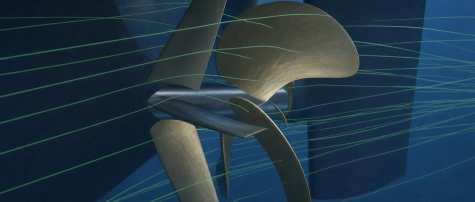
A vortex structure also develops around the propeller hub, associated with the flow around the blade roots and boss cap. This hub vortex develops in the region between the propeller and rudder. The distance between the two components and the shape of the front of the rudder partly determine how the flow behaves there.
For a PBCF or Rudder Bulb, this local interaction is particularly important. A PBCF changes the flow at the rotating boss cap, while a Rudder Bulb acts on the same flow region from the rudder. Both devices can therefore influence the hub flow, but the change in the forces on the propeller and rudder need not be the same.
Their combined operation also makes clear why greater propeller thrust at an unchanged rotational speed does not automatically mean higher propulsion efficiency. The required propeller thrust may change when the forces on the hull, ESD and rudder change. For the ship, what ultimately matters is how much shaft power is needed to maintain the same speed.
Which Interactions Guide ESD Selection?
The hydrodynamic diagnosis helps determine where an ESD can offer an improvement. A distinction can be made between the inflow ahead of the propeller, the flow around the propeller hub and the use of the flow behind the propeller. These regions are not independent of one another, but they do call for different technical research questions.
Where a change in inflow direction may offer a benefit, a Pre-Swirl Stator can be investigated. The fixed fins generate controlled pre-swirl, generally in the opposite direction to propeller rotation. As a result, the relative inflow angle of the propeller blades changes, and the propeller can deliver the required thrust with a more favourable energy distribution.
The stator itself also exerts hydrodynamic forces. Depending on the geometry and flow, their axial component may be favourable or unfavourable. Flow losses also occur around the fins. An assessment that looks only at the changed propeller loading may therefore give an incomplete picture of overall propulsion performance.
A Pre-Duct also influences the inflow ahead of the propeller, but uses a duct profile to do so. The geometry can change both the local velocity distribution and the inflow direction. The pressure distribution on the duct profile also produces a hydrodynamic force of its own. Some designs combine the duct with stator fins, so that flow guidance and pre-swirl are influenced together.
Favourable Pre-Duct performance therefore need not result solely from a more uniform wake field. What matters is how the modified inflow changes the propeller’s operation and the forces on the other components.
Other opportunities lie behind the propeller. A PBCF rotates with the propeller and influences the development of the flow around the boss cap. A Rudder Bulb is connected to the rudder and is matched to the space and flow behind the propeller hub. Both devices act partly on the same flow region, but from their different positions they do not necessarily influence the same forces.
The presence of a strong hub vortex is therefore not sufficient grounds for choosing directly between a PBCF and Rudder Bulb. First, the role of the existing propeller hub and front of the rudder in the flow, and the net benefit that a modification there can offer, must be clear.
The hydrodynamic diagnosis thus determines which ESD mechanisms are technically promising. Determining which individual device is then preferable requires a comparison of suitable designs within the actual ship configuration.
What Does PBCF Research Show About the Influence of the Rudder?
The influence of the rudder on an ESD is evident, among other things, from research into Propeller Boss Cap Fins. In an experimental and numerical comparison in 2016, the changes in PBCF hydrodynamic performance with different rudder configurations behind the propeller were investigated.
At the design operating point investigated, with an advance coefficient J of 0.8, an efficiency improvement due to the PBCF of 1.47% was reported without a rudder. For the configuration with a conventional rudder, 1.08% was reported, and for the design with a twisted rudder, 1.16%. The study combined cavitation tunnel tests with numerical flow analyses.
The percentages describe the propeller and rudder arrangements investigated. They are not measured annual fuel savings for a complete seagoing ship at full scale. The difference of 0.08 percentage points between the two rudder variants is also too small to substantiate a general preference for a particular rudder shape without an appropriate uncertainty assessment.
The main finding concerns the hydrodynamic interaction. The PBCF changed the flow around the boss cap, but in doing so also influenced the forces on the rudder behind it. In the configurations investigated, part of the favourable PBCF effect was offset by a less favourable contribution from the rudder. The study thus shows why a device around the propeller hub cannot be assessed solely on local vortex reduction. The influence on rudder loading partly determines how much benefit remains for the combined propeller–rudder arrangement.
The same principle applies to ESDs positioned ahead of the propeller, although the operating mechanism differs. A Pre-Swirl Stator changes the inflow direction and thus potentially the propeller loading and remaining rotation in the propeller slipstream. The rudder then receives a different inflow and may consequently develop different forces.
The influence of the rudder is therefore not a fixed correction factor that can subsequently be applied to a calculated ESD saving. The interaction must form part of the configuration investigated.
How Is the Hydrodynamic Diagnosis Translated into a Suitable ESD?
A well-founded ESD selection starts with the existing propulsion configuration. The stern shape, propeller geometry, hub construction and rudder arrangement jointly determine where relevant hydrodynamic losses may occur and which changes are technically possible.
For an existing ship, it must be checked whether the available data correspond to the actual configuration. A previous propeller replacement or rudder modification may have changed the matching between the components. If the original drawings are insufficiently reliable for this purpose, targeted inspections or geometric measurements may be needed.
Promising ESD mechanisms are then selected on the basis of the flow phenomena identified. The question is not only where the device is placed, but above all what change in flow and forces is expected.
Suitability must then be assessed for the complete propulsion configuration. Hydrodynamic calculations and, where necessary, model tests can be used for this purpose. In Computational Fluid Dynamics (CFD), propeller modelling must be sufficiently accurate to describe the interactions that are decisive for the device concerned. Geometric details may be particularly important around the hub and blade roots.
For the performance comparison, the configurations investigated must deliver the same ship performance. At corresponding speed through the water, draught and trim, the shaft power required by each design can be determined. The rotational speed, torque and individual forces on the propeller, rudder and ESD need not remain the same. It is the combined change in these quantities that determines the net power demand.
The prediction method must also suit the device investigated. Not every ESD has the same scale effects or places the same demands on modelling. A positive result at model scale is therefore not directly transferable to a full-scale ship without appropriate substantiation.
Alongside the hydrodynamic improvement, the technical consequences must remain acceptable. Changed propeller loading may influence cavitation, pressure fluctuations and vibration. For devices around the rudder, steering performance and manoeuvring characteristics must also remain adequate. The available space and structural possibilities further determine which geometries can actually be used.
A promising ESD need not deliver the same saving under all operating conditions. The operating behaviour investigated must therefore correspond to the speeds, draughts and propeller loads relevant to the ship. Favourable performance at the nominal design speed is less valuable if the ship rarely operates at that speed in service.
Hull–propeller–rudder interaction therefore does not directly determine that a particular ESD type is suitable for every comparable ship. The interaction shows which flow phenomena influence propulsion performance and where an additional device can offer an improvement. A Pre-Swirl Stator, Pre-Duct, PBCF or Rudder Bulb constitutes a suitable solution only when the expected change for the ship concerned has been investigated with sufficient reliability and the combined propulsion system requires less shaft power under the relevant operating conditions.
This Article Within the Series
When choosing between a Pre-Swirl Stator, Pre-Duct, PBCF and Rudder Bulb, the available installation space and existing propeller–rudder arrangement also matter alongside the hydrodynamic operation. How the operational profile, propeller type and possible combinations of devices influence that choice is discussed in matching ESDs to ship propulsion.