

When Should You Choose a Pre-Swirl Stator, Pre-Duct, PBCF or Rudder Bulb as an ESD?
Author: Jeroen Berger • Publication date:
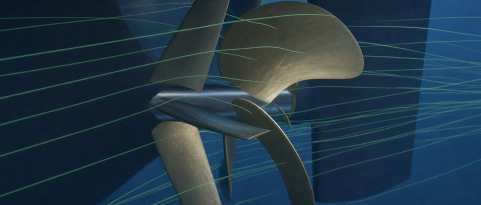
The choice between a Pre-Swirl Stator (PSS), Pre-Duct, Propeller Boss Cap Fins (PBCF) and Rudder Bulb depends on the hydrodynamic losses that can be reduced on a ship. A Pre-Swirl Stator is a candidate when controlled pre-swirl can help the propeller operate more efficiently. A Pre-Duct is particularly relevant when modified flow guidance towards the propeller plane offers an improvement. Around the propeller hub, a PBCF can reduce losses, while a Rudder Bulb can improve the flow between the propeller hub and rudder. Which Energy Saving Device (ESD) is preferable is partly determined by the stern shape, propeller geometry, rudder arrangement and available installation space. The operational profile also matters, because the hydrodynamic contribution can change under different loads. Ultimately, the suitable device is not the one that produces the strongest local change in flow, but the design with which the ship requires less shaft power under the relevant operating conditions.
Which Hydrodynamic Improvement Determines the Initial Choice?
A targeted ESD selection starts with investigating the flow around the existing or planned propulsion system. A distinction is made between the inflow ahead of the propeller, the flow that the propeller leaves behind and the interaction with the rudder. These regions offer different opportunities for improvement, but also influence one another. After all, a modification ahead of the propeller changes the loading on the blades and thus the flow towards the rudder.
The stern shape gives an initial indication of the devices that can be investigated. On relatively full, slower ships, such as certain bulk carriers and tankers, the flow towards the propeller plane can be highly non-uniform. A Pre-Duct may then offer opportunities to guide the inflow more favourably. In other configurations, controlled pre-swirl may offer a greater benefit. Pre-Swirl Stators are used on more slender and faster ships, among others, but may also be promising on ships with a fuller aftship. Hull shape alone therefore does not determine the choice.
What matters more is which change actually helps the existing propeller. A non-uniform wake field does not need to be made as uniform as possible. The speed and direction of the inflow jointly determine the relative inflow angle at the propeller blades. A targeted change in that angle can distribute propeller loading more favourably, even when the axial velocity distribution does not become more uniform everywhere. Conversely, a device that visibly improves the wake field may still cause additional drag.
Behind the propeller, a distinction must be made between losses around the hub and the influence of the propeller slipstream on the rudder. A strong hub vortex may be a reason to investigate a PBCF, but the same flow is also influenced by the existing rudder geometry. If a Rudder Bulb can favourably change the pressure distribution and flow between the propeller hub and rudder, that solution may also be promising.
The initial technical assessment must therefore establish where improvement is possible, which device addresses it and how the other propulsion components respond. A targeted selection of operating principles that warrant further investigation for the ship concerned emerges from this.
When Is a Pre-Swirl Stator Preferable to a Pre-Duct?
A Pre-Swirl Stator (PSS) is particularly promising when modified inflow rotation helps the propeller deliver the required thrust with less power. Fixed fins ahead of the propeller impart controlled rotation to the water in the opposite direction to propeller rotation. As a result, the relative inflow angles and the distribution of loading across the propeller blades change. With suitable matching, less rotational energy may remain in the final propeller slipstream.
The benefit depends strongly on the distribution of pre-swirl across the propeller plane. A stator that locally generates excessive or unfavourably directed pre-swirl may instead worsen propeller loading. The fins also produce their own hydrodynamic forces and flow losses. The deciding factor is therefore not how much pre-swirl is possible, but which stator geometry allows the complete propulsion system to perform most favourably.
A Pre-Duct follows a different design approach. The duct profile influences the speed and direction at which the water reaches the propeller plane. The pressure distribution on the duct also produces hydrodynamic forces of its own. Depending on the design and local flow, these forces may contribute favourably to propulsion or cause additional drag. Unlike a nozzle around a propeller, a conventional Pre-Duct is positioned ahead of the propeller plane.
A Pre-Duct may be a worthwhile avenue of investigation, particularly for a full stern with an unfavourable inflow distribution. The duct can change the flow towards certain parts of the propeller plane and thereby improve propeller performance. The shape, diameter and position determine the magnitude of that contribution. A more favourable velocity distribution is not sufficient, however, if the duct profile itself causes excessive hydrodynamic losses.
The distinction between the two devices is less absolute than their names suggest. A Pre-Swirl Stator can also influence the axial inflow, while certain duct designs with stator fins produce both flow guidance and pre-swirl. An integrated Pre-Swirl Duct combines these operating principles. When choosing separately between a stator and a conventional Pre-Duct, the main consideration remains which mechanism provides the greatest net improvement in the ship configuration under investigation.
When controlled pre-swirl favourably influences propeller loading and the remaining rotation in the propeller slipstream, a Pre-Swirl Stator may be preferable. If a modified axial inflow and the associated forces on the duct profile offer greater benefit, a Pre-Duct may be more suitable. That difference must be assessed against the same propulsion objective, because higher propeller thrust alone does not mean a lower shaft power requirement.
The available installation space can also change the preference. A Pre-Swirl Stator requires suitable attachment points and sufficient space to install the fins in the desired position. A Pre-Duct needs space for the profile and supporting structure. If the hydrodynamically desired geometry proves impracticable, an alternative design with a slightly smaller calculated improvement may still be the better technical solution.
When Should You Choose a PBCF or Rudder Bulb?
When the potential for improvement lies mainly around the propeller hub and the rudder behind it, Propeller Boss Cap Fins (PBCF) and a Rudder Bulb are candidates. Both influence the flow in this region, but from different positions. A PBCF is attached to the rotating boss cap and interacts directly with the propeller. A Rudder Bulb is attached to the rudder and influences the transition between the propeller hub and rudder.
A PBCF particularly warrants investigation when the hub flow can be influenced in a way that allows the propeller to operate more efficiently. The fins are matched to the geometry of the propeller blades, the boss cap and the local flow around the blade roots. The strength of the hub vortex can thereby be reduced. The hydrodynamic forces on the fins themselves also contribute to the final result. A favourable design can, among other things, improve the pressure distribution around the boss cap and reduce the required propeller torque.
The performance of a PBCF cannot, however, be inferred solely from the reduction in the hub vortex. The fins also change the flow towards the rudder. Research on propeller–rudder arrangements shows that a PBCF can increase rudder drag, making the improvement in overall propulsion smaller than for a propeller investigated in isolation. The existing rudder geometry must therefore be included in the assessment.
On an existing seagoing ship, a PBCF can enable a relatively targeted retrofit because the device is installed on the boss cap. This is particularly attractive when the existing propeller geometry can be retained and the hub structure is suitable for a modified cap. The shape and attachment must, however, suit the specific propeller. A PBCF can also be used on certain controllable pitch propellers, but not every hub structure can structurally accommodate a PBCF.
A Rudder Bulb is more likely to be suitable when the geometric and hydrodynamic matching between the propeller hub and rudder offers scope for improvement. The bulb is matched to the shape of the boss cap, the propeller slipstream and the existing rudder contour. The relative alignment, distance and pressure distribution around the front of the rudder particularly influence its performance. A favourable design can reduce losses around the hub vortex and improve the flow between the propeller and rudder.
The Rudder Bulb must be developed as part of the complete propeller–rudder arrangement. A different bulb shape not only influences the flow behind the propeller, but may also change the drag, pressure distribution and forces on the rudder. Its development must therefore go beyond assessing a streamlined enlargement at the leading edge. Behaviour at relevant rudder angles must also be checked.
The existing structure may provide an important distinction. For a PBCF, the boss cap, attachment and available space towards the rudder are key factors. A Rudder Bulb requires a suitable rudder shape and sufficient distance from the rotating propeller components. Particularly when the propeller–rudder distance is limited, the available clearances and possibilities for structural modification may influence the choice.
Nor is there a fixed order of preference in hydrodynamic terms. Both devices may partly address the same losses. If the existing rudder already favourably influences the flow around the propeller hub, the additional improvement from a PBCF may be limited. Conversely, a PBCF may change the hub flow in such a way that a separate Rudder Bulb adds less. A comparison must therefore relate to the actual propeller–rudder arrangement, including any devices already present.
A PBCF is therefore not automatically preferable because a hub vortex is visible. Nor is a Rudder Bulb automatically more suitable as soon as sufficient space is available between the propeller and rudder. The choice follows from the improvement that the two devices can provide within the existing or planned configuration.
Which Ship Characteristics Can Change the Preferred Option?
The most hydrodynamically promising ESD must also suit the ship’s structure and operating conditions. The stern shape, propeller position, available space and existing appendages determine which geometries can be installed. Particularly in retrofit projects, the original ship structure may considerably restrict design freedom.
For a Pre-Swirl Stator or Pre-Duct, considerations include the position relative to the propeller plane and the possibilities for safely transferring hydrodynamic forces to the stern. A design may perform favourably in a calculation, but become less attractive structurally when heavy supports or extensive modifications to the aftship are necessary. Access to the device for inspection and maintenance also warrants attention.
For a PBCF, the boss cap, propeller structure and attachment possibilities play a greater role. For a Rudder Bulb, the existing rudder shape, propeller–rudder distance and required clearances are particularly important. The structural consequences may therefore differ considerably, even when the two devices show comparable hydrodynamic improvements.
The propeller type also influences the design assessment. For a Controllable Pitch Propeller, the relevant blade pitch settings and rotational speeds must be included. An ESD that performs favourably at a particular pitch setting need not retain the same power improvement at another blade pitch. Additional structural constraints may also apply to devices around the hub. For a fixed pitch propeller, the assessment calls for particular attention to the changing combination of ship speed, rotational speed and propeller loading.
The operational profile then determines under which conditions the expected improvement actually has value. A coastal tanker that regularly alternates between laden and ballast operations may require different design matching from a seagoing ship that operates for long periods at an almost constant draught and cruising speed. The main operating conditions must therefore form part of the assessment. What matters is not only the greatest improvement at an individual operating point, but also how much time the ship actually spends operating under those conditions.
Alongside the power improvement, cavitation, vibration and manoeuvrability warrant attention. A modified inflow can distribute loading on the propeller blades more favourably, but may also cause unwanted pressure fluctuations under other operating conditions. For rudder devices, steering performance at relevant rudder angles must also be maintained. A favourable power prediction therefore does not replace an assessment of these characteristics.
Technical integration may make an initially attractive ESD less suitable. Conversely, a slightly less favourable device hydrodynamically may gain preference when the structural modifications are more limited and performance remains sufficiently reliable across the required operating range.
How Is the Final ESD Choice Made?
The initial hydrodynamic assessment determines which ESD types are promising for the ship. The most suitable designs are then compared under equivalent conditions. Not every device needs to be investigated to the same extent. If the existing geometry or flow leaves little prospect for a particular operating principle, that type may drop out at an early stage.
For the remaining candidates, the shaft power required by the ship at the same speed, draught and trim is determined. The forces on the hull, propeller, rudder and ESD are considered together. The required rotational speed and torque may differ between designs. Higher propeller thrust at the same rotational speed or a more favourable flow pattern alone therefore does not give a complete picture of the propulsion improvement.
The chosen calculation and investigation methods are important in this comparison. Calculations using Computational Fluid Dynamics (CFD) can reveal differences in flow, forces and power requirements. Model tests offer additional opportunities to check the predicted performance. For devices that change the inflow ahead of the propeller, scale effects must also be treated carefully. The relationship between axial and tangential changes in inflow in particular may influence the prediction of full-scale power requirements.
A comparative research project for a Handymax bulk carrier shows how such a choice may proceed in practice. A Pre-Swirl Stator, Pre-Duct and Rudder Bulb were designed and hydrodynamically assessed for the same ship. Following a comparison of all three, the Pre-Swirl Stator was selected and further developed for use on the ship. Alongside hydrodynamic performance, cavitation risks and practical feasibility also played a role. The selected stator was then tested at full scale. The outcome shows that different ESD principles can be promising for the same ship configuration, while a specific design ultimately gains preference. The comparison did not include a PBCF and does not establish a general ranking for other bulk carriers or ship types.
When several designs deliver a comparable power improvement, the reliability of the prediction and technical integration carry more weight. A small calculated difference need not be decisive when it falls within the uncertainty of the assessment method used. In that case, a design with simpler attachment, better maintenance access or less extensive modifications may be preferable.
It must also be clear which configuration is actually being compared. A separate Pre-Swirl Stator with the existing propeller is not the same as a jointly optimized combination of stator and new propeller. Both may be technically suitable solutions, but the calculated power improvements relate to different design assumptions. Those assumptions must remain identifiable for a reliable comparison.
The final assessment must also distinguish between shaft power and fuel consumption. A predicted reduction in required shaft power does not necessarily amount to an equally large percentage fuel saving. How the engine performs under the changed load and how many operating hours the ship accumulates at the relevant speeds and loads must be investigated for this purpose.
The choice of a Pre-Swirl Stator, Pre-Duct, PBCF or Rudder Bulb thus follows from the losses that can actually be reduced on the ship concerned. A Pre-Swirl Stator is preferable when controlled pre-swirl provides the greatest reliable net improvement. A Pre-Duct is more suitable when flow guidance and the forces on the duct profile produce a more favourable outcome. For losses around the propeller hub and rudder, the performance of the complete propeller–rudder arrangement determines whether a PBCF or a Rudder Bulb is the best solution.
If none of these devices delivers a sufficiently substantiated power improvement under the relevant operating conditions, it may be technically wiser not to install an ESD. Ultimately, the demonstrable contribution to efficient propulsion that can be responsibly implemented determines the choice, rather than the type of device.
This Article Within the Series
The choice between the four ESD types starts with the interaction between the hull, propeller and rudder. The saving that a suitable device can deliver in service also depends on the influence of the operational profile on ESD performance. Both aspects come together in matching ESDs to ship propulsion.