

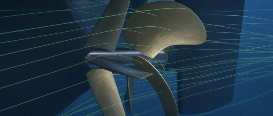
How Does the Operational Profile Affect the Performance of an Energy Saving Device (ESD)?
Author: Jeroen Berger • Publication date:
The operational profile determines under which conditions an Energy Saving Device (ESD) can improve a ship’s propulsion efficiency. Changes in ship speed, draught, trim and propeller loading influence the flow around the stern and the performance of the propeller and rudder. The same ESD may therefore deliver a different power saving under different operating conditions. A Pre-Swirl Stator (PSS), Pre-Duct, Propeller Boss Cap Fins (PBCF) or Rudder Bulb is matched to specific flow conditions, but often has to function across a wider operating range in service. A design that performs well at the nominal cruising speed may also offer a benefit at other speeds and loading conditions. The magnitude of that improvement need not remain the same, however. For suitable matching, what matters is how the ship is actually used, under which operating conditions the most propulsion power is needed and how many hours it operates under those conditions. An ESD can thus be developed that performs favourably beyond a single design operating point and matches the ship’s actual use.
Why Does ESD Performance Change with Ship Speed?
When a ship sails faster, resistance generally increases and the propeller must deliver more thrust. Depending on the propulsion installation, the propeller rotational speed, blade loading and speed at which the water reaches the propeller plane change. The ratio between the axial inflow and the circumferential speed of the propeller blades is particularly important to hydrodynamic performance. This ratio influences the relative inflow angles and thus the forces that develop on the blades.
A change in speed need not always alter this ratio to the same extent. When inflow speed and rotational speed change approximately in proportion, the hydrodynamic operating point of the propeller may change relatively little. With a different ratio between the two quantities, blade loading and the flow behind the propeller may instead differ more substantially. The distribution of inflow across the propeller plane also remains important. Even when the average ratio between inflow speed and rotational speed remains approximately the same, the wake field behind the hull need not retain the same characteristics. Ship speed alone is therefore insufficient to predict how much benefit an ESD will deliver.
For a Pre-Swirl Stator, the way in which the fixed fins generate pre-swirl and the rotating propeller responds to it changes with operating conditions. The stator influences the relative inflow to the propeller blades, but a favourable distribution of that inflow also depends on propeller loading and the local wake field. A stator that is well matched at one operating point may therefore make a smaller or larger contribution at another combination of ship speed and rotational speed.
A Pre-Duct influences flow guidance towards the propeller plane and itself experiences hydrodynamic forces. When speed and loading change, the pressure distribution on the duct profile and the interaction with the propeller may also shift. Favourable flow guidance at the nominal cruising speed therefore does not mean that the duct delivers the same power improvement at every other speed. The final result also depends on the relationship between the improvement in propeller performance and the forces that the duct itself produces.
Behind the propeller, the flow with which the devices interact also changes. The characteristics of the propeller slipstream and the flow around the hub are related to propeller loading. The influence of a PBCF on the hub vortex may therefore differ at each operating point. For a Rudder Bulb, the pressure and velocity distribution with which the propeller slipstream reaches the rudder may change. In both cases, the influence on the complete propeller–rudder arrangement matters, rather than the local change in flow alone.
A lower or higher speed does not automatically mean that an ESD becomes less efficient. Some designs retain favourable performance across a broad speed range. Other geometries are more sensitive to deviations from the original design operating point. The relevant question is therefore not only how large the improvement is at cruising speed, but also how the device performs within the speed range in which the ship is actually used.
How Do Draught and Trim Affect ESD Performance?
With a different loading condition, the hull sits differently in the water. The submerged hull shape, resistance and flow around the stern may therefore differ from the original design condition. This may affect propeller inflow, particularly on seagoing ships that regularly alternate between laden and ballast operations.
A coastal tanker may, for example, sail at a considerably greater draught on a laden voyage than on the return voyage in ballast. The propeller and any ESD retain the same position relative to the aftship, but the flow around these components may change with hull immersion. The required thrust may also differ considerably between the two loading conditions at a comparable ship speed. The influence of loading therefore arises through both the changing ship resistance and the modified inflow to the propulsion system.
For a Pre-Swirl Stator or Pre-Duct, the way in which the distribution of velocity and flow direction ahead of the propeller plane changes is particularly important. A different draught may affect the wake field, as a result of which the stator fins or duct must interact with a modified inflow. The pre-swirl generated, flow guidance and forces on the device may therefore differ from the condition for which the design was originally optimized.
The performance of a PBCF or Rudder Bulb may also change. Different propeller loading influences the flow around the blade roots and boss cap, and the propeller slipstream that reaches the rudder. For the PBCF, this may affect the relationship between its influence on the hub vortex and the forces on the fins themselves. A Rudder Bulb encounters a potentially different velocity and pressure distribution around the transition between the propeller hub and rudder.
With less propeller immersion, the influence of the free water surface may also increase. Its significance depends on the propeller position, the available depth of water above it and the operating conditions. When the propeller comes to lie relatively close below the surface, ventilation and cavitation problems may occur or increase under unfavourable conditions. Propulsion performance may consequently change more than would be expected from the change in ship resistance alone. The assessment must therefore also account for propeller immersion at relevant ballast and trim conditions.
Trim influences the flow in a different way. At the same mean draught, a ship may have different fore and aft draughts. The submerged stern shape and the position of the propeller relative to the water surface change as a result. Ship resistance may also change. A change in trim can therefore simultaneously influence the required propeller thrust and the local inflow to an ESD.
A device that delivers a favourable power saving under fully laden conditions need not achieve the same improvement in ballast. Conversely, a design matched to several loading conditions may also perform well away from the original design draught. The technical assessment must therefore correspond to the draughts and trim conditions that actually matter in service.
What Do Propeller Loading, Rotational Speed and Blade Pitch Mean?
Propeller loading is not determined solely by ship speed. A seagoing ship may require more thrust at the same speed through the water when wind and waves cause additional resistance. Fouling and increasing hull roughness may also increase the required loading. The propeller then operates under different hydrodynamic conditions, although ship speed has hardly changed. In a seaway, ship motions and the varying inflow around the stern may also influence instantaneous propeller behaviour.
For a fixed pitch propeller, the relative inflow to the blades changes when the ratio between inflow speed and rotational speed shifts. The local angles of attack, blade loading and flow behind the propeller change as a result. Under these conditions, a Pre-Swirl Stator must generate pre-swirl that still interacts favourably with the propeller. PBCF performance may also shift, because changing blade loading influences the flow around the blade roots and boss cap.
For a Controllable Pitch Propeller (CPP), adjustable blade pitch is an additional factor. A CPP can deliver the required thrust with different combinations of pitch and rotational speed, depending on the installation and control strategy. When blade pitch changes, the geometric orientation of the propeller blades changes. In combination with the relative inflow, this influences the hydrodynamic angle of attack and loading of the blades.
For an ESD, this means that two operating settings at comparable ship speeds may still produce different flow conditions. Blade pitch may, for example, change while propeller rotational speed remains almost constant. The flow around the hub and the propeller slipstream towards the rudder may then differ from those in an installation where rotational speed varies more substantially. ESD performance must therefore be assessed in conjunction with the actual operation and control of the propeller.
During manoeuvring, conditions often differ even more substantially from normal ahead operation. Large changes in blade pitch, rotational speed or rudder angle influence the direction and distribution of flow around the propulsion system. An ESD designed mainly for favourable performance at cruising speed need not deliver a comparable efficiency improvement in these situations. The device must, however, withstand the relevant hydrodynamic loads and must not unacceptably affect the required manoeuvring and steering performance. There is therefore an important distinction between the operating settings for which energy savings are optimized and the conditions under which the installation must be able to function technically. Not every manoeuvring condition needs to carry equal weight in the expected energy saving, but technical suitability must be maintained throughout the required operating range.
Why Is the Most Favourable Design Operating Point Not Always Decisive?
An ESD may show a clear power improvement at a particular combination of speed, draught and propeller loading. That result does not, however, automatically indicate how much benefit the device delivers throughout service. What matters for this is how often the ship operates under those conditions and how much propulsion power is required.
Consider a coastal tanker that alternates between laden and ballast operations. On laden voyages, more propulsion power is generally required at a comparable speed. An ESD that delivers a modest percentage improvement under those conditions may still save more propulsion energy per sailing hour than a device that achieves a higher saving percentage in ballast. The reverse may also occur when the hydrodynamic performance is distributed differently.
Operating duration also plays a role. A ship may spend many hours at a relatively low speed, while shorter periods of higher power demand account for a considerable share of energy consumption. The highest saving percentage at an individual operating point therefore need not coincide with the greatest contribution to energy savings across the operational profile.
For the assessment, it is therefore determined at each representative operating point how much shaft power is required with and without an ESD at the same speed through the water and under the same relevant ship and environmental conditions. The power difference in kilowatts is then linked to the number of operating hours under those conditions. An assessment of the total shaft energy saved results from combining the contributions across the operational profile. Operating points at which the device offers less benefit or requires additional power also count. A simple average of individual saving percentages does not give a reliable result for this purpose.
For a ship that operates almost continuously within a narrow speed and load range, targeted optimization for that range may be attractive. With highly variable operations, a design that retains a favourable improvement under several frequently encountered conditions may better match actual use. A broader performance improvement is not automatically more important than a pronounced optimum. The distribution of operating hours and required power determines which performance results warrant the greatest weight.
For the assessment, a distinction remains necessary between the hydrodynamic power reduction and the eventual fuel saving. A lower shaft power demand means that less propulsion energy is required to deliver the same ship performance under the same conditions. How this affects fuel consumption also depends on engine loading, specific fuel consumption and the characteristics of the propulsion installation. The shaft energy saved therefore cannot be translated directly into the same percentage fuel saving without further assessment.
How Is an ESD Matched to the Operational Profile?
A suitable ESD is developed from the operating conditions that actually matter for the ship. The main speeds and loading conditions are linked to the corresponding draught, trim and propeller loading. For a CPP, the usual combinations of blade pitch and rotational speed are also included. These data show under which conditions the device must function for most of the time and where a power improvement may have the greatest value.
When compiling the operational profile, a distinction must be made between speed through the water and speed over the ground. The hydrodynamic inflow to the hull and propeller is related to the ship’s motion relative to the water. A changing current may affect speed over the ground without the hydrodynamic operating condition changing to the same extent. Loading, trim and relevant weather and wave conditions must also remain identifiable in the data. Otherwise, different operating conditions may incorrectly be treated as comparable.
The available operating data need not lead to a separate design calculation for every voyage. Conditions with similar hydrodynamic characteristics can be grouped into representative operating points. Differences that materially change inflow, propeller loading or ESD performance must, however, remain separately identifiable. A coastal ship that sails both laden and in ballast at different speeds may therefore need more representative operating points than a seagoing ship with a relatively constant operational profile.
How the ESD interacts with the existing propulsion system under these conditions is then investigated. This concerns not only the flow around the device, but also the changed propeller loading and the forces on the hull and rudder. Calculations or model tests at different operating points can reveal whether favourable performance remains limited to a single design condition or extends across a larger part of the operational profile. When predicting full-scale performance, the limitations and uncertainties of the investigation method used must also be taken into account.
The geometry of a Pre-Swirl Stator, Pre-Duct or PBCF generally remains unchanged during normal operation. A Rudder Bulb also retains the same shape, although its position relative to the propeller slipstream changes with rudder angle. These devices therefore cannot be set optimally for every individual speed and propeller loading. The design calls for a balance between performance at the main operating points and behaviour under different conditions.
If a particular geometry offers the greatest benefit at the nominal cruising speed but performs considerably less favourably at other frequently used operating settings, a modified design may be preferable. This need not always be an entirely different ESD type. A change in the orientation or geometry of the fixed stator fins, a modified duct profile or a different hub-fin configuration may influence the distribution of performance across the operating range. Which modification is worthwhile depends on the ship concerned and the hydrodynamic performance of the device.
Changes in future deployment also warrant attention. A bulk carrier that adopts consistently lower speeds or a coastal ship whose balance between laden and ballast voyages changes may operate more often under different conditions than originally expected. An ESD closely matched to the old design operating point may therefore no longer deliver the same energy saving in service.
The operational profile influences the performance of an Energy Saving Device because speed, draught, trim and propeller loading change the flow around the device and the existing propulsion system. The power reduction at each operating point may therefore also shift. A suitable design consequently takes account of the conditions under which the ship actually uses propulsion energy and the technical requirements outside the main operating range. An ESD thus emerges that not only performs favourably under ideal design conditions, but can deliver a technically sound improvement during the ship’s actual operations.
This Article Within the Series
When selecting a Pre-Swirl Stator, Pre-Duct, PBCF or Rudder Bulb, both the operating principle and the conditions under which the device offers a benefit matter. A further design question is how ESD matching differs between a fixed pitch propeller and a CPP, with blade pitch, rotational speed and hub structure among the relevant factors. These considerations come together in the broader relationship between ship propulsion and ESD configuration.