- English
- Nederlands

Suction Sails
Suction sails are wind-assisted propulsion systems (WAPS) that use active boundary-layer suction to generate aerodynamic lift. Part of the resulting force can assist the vessel in the direction of travel, reducing the propeller power required at the same vessel speed. Project references and vessel-specific calculations show that fuel savings of around 15–20% may be possible, depending on factors including the vessel, route, wind conditions and sail configuration. The associated CO2 emissions may therefore also decrease accordingly. The system combines an aerodynamic profile with a movable trailing flap, electrically powered suction and automatic orientation to the apparent wind. The height, number and position of the suction sails are matched to the operational profile, available deck space and shipboard systems. The expected wind contribution and electrical consumption are considered together, with attention to stability, structural loads and daily deck operations. Together with a specialist international partner, we support shipping companies and shipowners with feasibility assessment, selection of a suitable configuration, and the subsequent engineering, implementation and commissioning of suction sails for retrofits and newbuild seagoing and coastal vessels.
Available worldwide
Boundary-Layer Suction, Profile Shape and Trailing Flap
A boundary layer forms along the aerodynamic profile, in which the air close to the surface is slowed down. At a higher angle of attack, the flow may separate, reducing lift and increasing drag. An electrically driven axial fan draws air out of this boundary layer through a porous section of the surface. Flow separation is thereby delayed, allowing the profile to produce more lift under suitable conditions.
The movable trailing flap adjusts the profile shape to the wind direction. Depending on the side from which the apparent wind approaches, the flap is positioned on the appropriate side of the profile. The suction area that is not in use is covered. A separate electric drive with a slewing ring bearing orients the main structure to the wind. Unlike a rotor sail, where lift results from the continuous rotation of a cylinder, this suction sail relies on the combined action of profile shape, flap position and active suction.
For the same sail area, the active profile can generate approximately six to seven times as much lift as a conventional sail without active suction under suitable conditions. Fuel savings then also depend on the share of aerodynamic force acting in the direction of travel, the electricity required for suction and the vessel’s response to wind loading.
Apparent Wind and Vessel Response Determine the Usable Force
A suction sail uses apparent wind: the airflow a vessel under way experiences. This results from the combination of true wind with the vessel’s speed and direction of movement. The same weather conditions can therefore produce a different propulsion contribution at a different heading or vessel speed.
For propulsion, the forward component of the total aerodynamic force matters. The lateral force may also affect vessel leeway and the rudder corrections required. Heeling and yawing moments also depend on the direction and point of application of the force. These responses are included, together with hull and rudder resistance, when calculating the required propeller power.
For the performance assessment, wind data spanning several years along the route are linked to vessel speeds, heading distribution, seasons and operating hours. This shows how often usable combinations of wind direction and speed occur during the intended voyages. This distribution provides the basis for the expected use of the suction sails over the operational profile.
When Are Suction Sails Worth Investigating?
Suction sails may be particularly attractive for vessels spending sufficient hours at sea or in coastal waters on routes where usable combinations of wind direction and speed occur regularly. Average wind speed alone provides insufficient insight. Heading distribution, vessel speed, seasons and the share of operating hours also determine how much wind can actually be used to assist propulsion.
Sufficient deck space must also be available. Suction sails need positions with sufficient unobstructed inflow, without unnecessarily restricting daily vessel operations. Hatches, cranes, manifolds, pipework, life-saving appliances and walkways also determine how many sails can be installed and where this is worthwhile.
Height restrictions can also be decisive early on. Where a vessel passes under bridges, calls at ports with restricted overhead clearance or carries out deck operations that require vertical space, a tilting design may be relevant. Sufficient space must then also be available for tilting and securing the system safely.
The vessel’s structure and stability must also be sufficient to accommodate the mass and wind loads of the selected arrangement. Electrical capacity is also needed for suction, profile orientation, flap adjustment and control. This load is assessed together with the other electricity demand on board. Net fuel savings depend on both the wind contribution and the installation’s own energy consumption.
An initial assessment therefore brings together routes, wind conditions, hours at sea, vessel speeds, deck layout, air draught, stability, structure and available electrical capacity. This allows it to be determined early on whether suction sails offer sufficient technical and operational potential for further development. It also shows which combination of number, height and position is most promising.
Automatic Control of Orientation, Flap and Suction
The automatic control system coordinates profile orientation, flap position and suction. Wind data are combined with navigation data and information on vessel motions for this purpose. The control system uses these inputs to control the drives within permissible operating limits.
The main structure and outer skin carry the loads and protect the equipment inside the suction sail. The central control cabinet receives electrical power from the vessel and distributes it to the control system and drives. Using the bridge controls, the crew can monitor system status, assess alarms and switch between permitted operating modes.
Because of automatic control, the crew need to do less manual trimming. The necessary actions and safe system positions are specified for port operations, maintenance and faults. If sensors, electrical power or a drive fail, it must be clear how the installation can reach a safe state. The wind load acting on the structure when suction is switched off remains relevant.
Model Range and Choice of Dimensions
The model range comprises three classes with different profile widths and heights, all with automatic control. The model, height and number of suction sails are selected together on the basis of the desired propulsion contribution, available space, electrical capacity and loads the vessel can accommodate.
Model 1 has a profile width of 3.5 metres, with versions from 16 to 20 metres high. A tilting system and an EX version for applications with explosion protection requirements are available as options. This model class may be investigated for applications including general cargo, multipurpose and feeder vessels.
Model 2 has a profile width of 4.5 metres, with versions from 22 to 26 metres high. A tilting system is optional. This model version has no EX option. Potential applications include Handysize bulk carriers, MR and LR1 tankers, Panamax vessels, ferries and ro-ro vessels.
Model 3 has a profile width of 6 metres, with versions including heights of 24, 32 and 36 metres. A tilting system can be used at selected heights. An EX version is also available as an option. This larger model class may be investigated for applications including larger tankers and bulk carriers.
Within these vessel groups, the vessel’s own operational profile and installation possibilities remain decisive for selection. The selected model, height, number of suction sails and available options are specified in the technical proposal. For an EX version, it is also checked whether the specification matches the hazardous zone in which the system is installed.
Matching Number and Position to Airflow and Deck Use
A suitable position provides sufficient unobstructed inflow while leaving space for daily work on deck. The superstructure, masts, cargo and other suction sails can affect local airflow. Cranes, hatches, manifolds, pipework and life-saving appliances must also remain accessible and usable.
Where there are several suction sails, their interaction with the airflow also matters. A sail in the disturbed flow from another sail may provide a different contribution from one in unobstructed inflow. With Computational Fluid Dynamics (CFD), this interaction and the effect of vessel geometry can be investigated.
For each additional suction sail, the extra propulsion contribution is weighed against the additional weight, electrical consumption, structural load and space requirements. The complete arrangement is therefore assessed as a whole. This shows which addition can provide sufficient added value over the actual operational profile.
Height, Tilting Capability and Safe Deck Operations
The required air draught is determined by the complete installation above the waterline. In addition to suction sail height, the foundation, deck height, draught and loading condition also count. The required clearance from obstructions is also taken into account for bridge passages and port calls.
An optional tilting system makes it possible to move the suction sail from a vertical to a horizontal position. This may help with height restrictions or certain loading and unloading operations. Sufficient deck space, suitable locks and defined operating limits are needed for tilting and securing. The permissible wind and vessel conditions during tilting are established for each version. The safe state in heavy weather is assessed separately.
Positioning also involves bridge visibility, radar coverage, navigation lights and safe walkways and escape routes. Crane movements, bunkering, maintenance and the use of life-saving appliances must remain possible. For classified hazardous zones, the applicable explosion protection requirements are linked to the selected position and version.
Foundations and Vessel Structure for Retrofits and Newbuilds
The suction sail is attached to a vessel-specific foundation with a bolted flange. Forces and moments are transferred through this foundation to the underlying vessel structure. The foundation, deck and adjoining frames, girders and bulkheads are therefore assessed together.
In addition to aerodynamic loading, the installation’s own weight and forces due to vessel motions also count. The structure is assessed for the relevant load combinations during use and in inactive states. Strength, stiffness and fatigue must be appropriate for these loads. The mass and centre of gravity of the suction sails and any reinforcements are also included in the vessel’s weight and stability assessment.
For retrofits, the existing vessel structure, electrical installation, cable routes and deck layout provide the starting point. Depending on the situation, deck reinforcement, foundation construction, cabling, connection to the bridge and relocation of deck equipment may be required. Lifting work, installation access and the sequence of work are also coordinated with the vessel and shipyard schedules.
For newbuilds, the foundations, electrical services, control system, deck layout and stability can be developed early on in conjunction with the sail positions. The vessel structure and system layout can therefore be matched directly to the selected arrangement.
Including Electrical Consumption and Engine Loading in the Savings
The wind supplies the energy for additional propulsion. Electricity is nevertheless needed for the suction fan, profile orientation, flap adjustment and control. The fan is the main electrical consumer. The power required varies with system settings and operating conditions.
To determine net fuel savings, the reduction in required propulsion power at the same vessel speed and the electricity the suction sails consume to achieve this are calculated. Both changes are linked to the fuel consumption of the energy sources concerned. The way electricity is generated and the efficiency of the main and auxiliary engines at their changed loading both count.
With a large wind contribution, the main engine may run at a lower load for prolonged periods. The permissible lower limits for continuous operation and specific fuel consumption at that operating point therefore remain part of the calculation. The operating strategy is matched to the available wind force and the propulsion plant’s operating limits.
From Performance Data to Annual Returns
The performance calculation links the aerodynamic forces of the selected version to apparent wind speed, angle of attack and system setting. The associated electrical consumption is also included. Together with vessel characteristics, this gives an estimate of the net propulsion contribution under different sailing conditions.
These performance figures are then linked to the intended voyages, seasons and operating hours. Periods with little usable wind, maintenance and restrictions during port or cargo operations also count. The installation’s added weight and drag are included where they affect propulsion demand. From the calculated difference in fuel consumption and the fuel types used, the expected CO2 reduction follows.
Weather routing can help make greater use of wind when safety, arrival time and commercial scheduling allow. In route selection, the benefits of wind assistance are weighed against additional distance, wave resistance and the sailing time required. A forecast using weather routing is therefore assessed separately from a calculation based on the existing sailing pattern.
Comparing different heights, numbers and positions shows which arrangement can offer sufficient usable wind hours and net returns. Limited deck space or electrical capacity may be a reason to choose another version. The technical and economic outcome then provides the basis for developing a configuration further, modifying it or deciding against the investment.
Assessing Net Performance in Operation
For operational performance verification, the contribution being investigated and its reference case are specified in advance. Speed, heading, engine or shaft power, fuel consumption, wind, draught, trim and sea state are recorded over the same periods. The system’s electrical consumption, suction, profile orientation and flap position are also linked to the measured data.
The position of anemometers and any corrections must take account of the effect of the superstructure and suction sails on local airflow. The speed data used and how the effect of current is accounted for are also specified. Changes in loading, hull condition and operation are included to distinguish their effect from the contribution of the suction sails.
On-off trials can, under suitable conditions, provide insight into the difference between active and switched-off wind assistance. However, the suction sails remain on board in both cases. For the total project contribution, the effect of the added installation relative to the original vessel must therefore also be assessed.
For a route or annual assessment, operational measurements are combined with a performance model for the other relevant wind and sailing conditions. Measurements and calculations thus complement one another while retaining the distinction between them. Results outside the conditions actually measured remain identifiable as calculated values. The measurement method, uncertainty and any acceptance agreements are matched to the purpose of verification.
Operational Results with Suction Sails on the Ville de Bordeaux
On the ro-ro vessel Ville de Bordeaux, three suction sails of 22 metres were assessed over twelve months by Bureau Veritas Solutions Marine & Offshore (BVS). Fuel savings of 568 tonnes were established over the year studied. The reported CO2 emissions reduction was 2,181 tonnes on a well-to-wake basis, including both the fuel supply chain and use on board.
BVS also reported average daily fuel savings of 1.7 tonnes, with peaks of up to 5.4 tonnes per day. The assessment combined onboard measurements with a vessel energy model that included hydrodynamic and aerodynamic loads, machinery and sail performance. The results were achieved without weather routing while carrying aircraft components between Europe and the United States.
Design Approval and Vessel-Specific Assessment
A Type Approval Design Certificate (TADC) has been issued by DNV for the suction sail design on the basis of DNV-ST-0511 for Wind-Assisted Propulsion Systems. A DNV TADC has also been issued for Model 3-24. A Design Assessment from Bureau Veritas is also available for this model.
During system selection, it is checked which design approvals apply to the chosen version and which components and options they cover. These approvals provide a starting point for the technical documentation. Installation and connection on the vessel concerned are also assessed separately.
The vessel-specific assessment includes the arrangement, stability, sightlines, navigation equipment, foundations, electrical connections, control, fire safety and safe operating states. The documentation is matched to the classification society involved and, where required, the flag State. Fuel savings are substantiated separately for the vessel, selected sail configuration and operational profile.
Maintenance of Suction and Moving Parts
Maintenance covers the fan and electric motor, porous suction area, flap and its drive, slewing ring bearing, sensors, electrical equipment and flange connection. These components must remain accessible for inspection, cleaning and replacement. On a tilting version, the tilting mechanism and locks are also included in the maintenance plan.
Fouling or blockage of the suction area may affect airflow and therefore aerodynamic performance and electrical consumption. Salt, moisture, corrosion, vibration and weather exposure also require attention to sealing, drainage and periodic inspection. Icing and safe access are also assessed on cold routes.
Maintenance planning is matched to operating hours, the operating area and the vessel’s scheduled maintenance periods. Both technical availability and the time when the suction sails are actually used are important to the expected annual returns.
Assessing Annual Savings and Project Costs Together
The business case starts with the expected net fuel savings for the selected operational profile. The suction sails’ electrical consumption is included once. The financial value is then determined from the relevant fuel prices and any other project returns that can be substantiated for the application.
The investment includes the suction sails, engineering, foundations, vessel reinforcements, electrical services, installation and commissioning. Maintenance, spare parts, additional shipyard time and any effects on deck or cargo operations also count. Different scenarios for wind availability, installation use and costs show how sensitive the business case is to these assumptions.
The expected savings are assessed over the vessel’s remaining service life and compared with the full investment and operating costs. This shows under which operational and financial conditions the selected arrangement offers sufficient potential.
Suction Sails
Together with a specialist international partner, we support shipping companies and shipowners with feasibility assessment, selection of a suitable configuration, and the subsequent engineering, implementation and commissioning of suction sails for retrofits and newbuild seagoing and coastal vessels.
Available worldwide
What Are Suction Sails?
Suction sails are wind-assisted propulsion systems (WAPS) that use active boundary-layer suction to generate aerodynamic lift. Part of the resulting force can assist the vessel in the direction of travel, reducing the propeller power required at the same vessel speed.
Project references and vessel-specific calculations show that fuel savings of around 15–20% may be possible, depending on factors including the vessel, route, wind conditions and sail configuration. The associated CO2 emissions may therefore also decrease accordingly.
The system combines an aerodynamic profile with a movable trailing flap, electrically powered suction and automatic orientation to the apparent wind. The height, number and position of the suction sails are matched to the operational profile, available deck space and shipboard systems.
The expected wind contribution and electrical consumption are considered together, with attention to stability, structural loads and daily deck operations.
Boundary-Layer Suction, Profile Shape and Trailing Flap
A boundary layer forms along the aerodynamic profile, in which the air close to the surface is slowed down. At a higher angle of attack, the flow may separate, reducing lift and increasing drag. An electrically driven axial fan draws air out of this boundary layer through a porous section of the surface. Flow separation is thereby delayed, allowing the profile to produce more lift under suitable conditions.
The movable trailing flap adjusts the profile shape to the wind direction. Depending on the side from which the apparent wind approaches, the flap is positioned on the appropriate side of the profile. The suction area that is not in use is covered. A separate electric drive with a slewing ring bearing orients the main structure to the wind. Unlike a rotor sail, where lift results from the continuous rotation of a cylinder, this suction sail relies on the combined action of profile shape, flap position and active suction.
For the same sail area, the active profile can generate approximately six to seven times as much lift as a conventional sail without active suction under suitable conditions. Fuel savings then also depend on the share of aerodynamic force acting in the direction of travel, the electricity required for suction and the vessel’s response to wind loading.
Apparent Wind and Vessel Response Determine the Usable Force
A suction sail uses apparent wind: the airflow a vessel under way experiences. This results from the combination of true wind with the vessel’s speed and direction of movement. The same weather conditions can therefore produce a different propulsion contribution at a different heading or vessel speed.
For propulsion, the forward component of the total aerodynamic force matters. The lateral force may also affect vessel leeway and the rudder corrections required. Heeling and yawing moments also depend on the direction and point of application of the force. These responses are included, together with hull and rudder resistance, when calculating the required propeller power.
For the performance assessment, wind data spanning several years along the route are linked to vessel speeds, heading distribution, seasons and operating hours. This shows how often usable combinations of wind direction and speed occur during the intended voyages. This distribution provides the basis for the expected use of the suction sails over the operational profile.
When Are Suction Sails Worth Investigating?
Suction sails may be particularly attractive for vessels spending sufficient hours at sea or in coastal waters on routes where usable combinations of wind direction and speed occur regularly. Average wind speed alone provides insufficient insight. Heading distribution, vessel speed, seasons and the share of operating hours also determine how much wind can actually be used to assist propulsion.
Sufficient deck space must also be available. Suction sails need positions with sufficient unobstructed inflow, without unnecessarily restricting daily vessel operations. Hatches, cranes, manifolds, pipework, life-saving appliances and walkways also determine how many sails can be installed and where this is worthwhile.
Height restrictions can also be decisive early on. Where a vessel passes under bridges, calls at ports with restricted overhead clearance or carries out deck operations that require vertical space, a tilting design may be relevant. Sufficient space must then also be available for tilting and securing the system safely.
The vessel’s structure and stability must also be sufficient to accommodate the mass and wind loads of the selected arrangement. Electrical capacity is also needed for suction, profile orientation, flap adjustment and control. This load is assessed together with the other electricity demand on board. Net fuel savings depend on both the wind contribution and the installation’s own energy consumption.
An initial assessment therefore brings together routes, wind conditions, hours at sea, vessel speeds, deck layout, air draught, stability, structure and available electrical capacity. This allows it to be determined early on whether suction sails offer sufficient technical and operational potential for further development. It also shows which combination of number, height and position is most promising.
Automatic Control of Orientation, Flap and Suction
The automatic control system coordinates profile orientation, flap position and suction. Wind data are combined with navigation data and information on vessel motions for this purpose. The control system uses these inputs to control the drives within permissible operating limits.
The main structure and outer skin carry the loads and protect the equipment inside the suction sail. The central control cabinet receives electrical power from the vessel and distributes it to the control system and drives. Using the bridge controls, the crew can monitor system status, assess alarms and switch between permitted operating modes.
Because of automatic control, the crew need to do less manual trimming. The necessary actions and safe system positions are specified for port operations, maintenance and faults. If sensors, electrical power or a drive fail, it must be clear how the installation can reach a safe state. The wind load acting on the structure when suction is switched off remains relevant.
Model Range and Choice of Dimensions
The model range comprises three classes with different profile widths and heights, all with automatic control. The model, height and number of suction sails are selected together on the basis of the desired propulsion contribution, available space, electrical capacity and loads the vessel can accommodate.
Model 1 has a profile width of 3.5 metres, with versions from 16 to 20 metres high. A tilting system and an EX version for applications with explosion protection requirements are available as options. This model class may be investigated for applications including general cargo, multipurpose and feeder vessels.
Model 2 has a profile width of 4.5 metres, with versions from 22 to 26 metres high. A tilting system is optional. This model version has no EX option. Potential applications include Handysize bulk carriers, MR and LR1 tankers, Panamax vessels, ferries and ro-ro vessels.
Model 3 has a profile width of 6 metres, with versions including heights of 24, 32 and 36 metres. A tilting system can be used at selected heights. An EX version is also available as an option. This larger model class may be investigated for applications including larger tankers and bulk carriers.
Within these vessel groups, the vessel’s own operational profile and installation possibilities remain decisive for selection. The selected model, height, number of suction sails and available options are specified in the technical proposal. For an EX version, it is also checked whether the specification matches the hazardous zone in which the system is installed.
Matching Number and Position to Airflow and Deck Use
A suitable position provides sufficient unobstructed inflow while leaving space for daily work on deck. The superstructure, masts, cargo and other suction sails can affect local airflow. Cranes, hatches, manifolds, pipework and life-saving appliances must also remain accessible and usable.
Where there are several suction sails, their interaction with the airflow also matters. A sail in the disturbed flow from another sail may provide a different contribution from one in unobstructed inflow. With Computational Fluid Dynamics (CFD), this interaction and the effect of vessel geometry can be investigated.
For each additional suction sail, the extra propulsion contribution is weighed against the additional weight, electrical consumption, structural load and space requirements. The complete arrangement is therefore assessed as a whole. This shows which addition can provide sufficient added value over the actual operational profile.
Height, Tilting Capability and Safe Deck Operations
The required air draught is determined by the complete installation above the waterline. In addition to suction sail height, the foundation, deck height, draught and loading condition also count. The required clearance from obstructions is also taken into account for bridge passages and port calls.
An optional tilting system makes it possible to move the suction sail from a vertical to a horizontal position. This may help with height restrictions or certain loading and unloading operations. Sufficient deck space, suitable locks and defined operating limits are needed for tilting and securing. The permissible wind and vessel conditions during tilting are established for each version. The safe state in heavy weather is assessed separately.
Positioning also involves bridge visibility, radar coverage, navigation lights and safe walkways and escape routes. Crane movements, bunkering, maintenance and the use of life-saving appliances must remain possible. For classified hazardous zones, the applicable explosion protection requirements are linked to the selected position and version.
Foundations and Vessel Structure for Retrofits and Newbuilds
The suction sail is attached to a vessel-specific foundation with a bolted flange. Forces and moments are transferred through this foundation to the underlying vessel structure. The foundation, deck and adjoining frames, girders and bulkheads are therefore assessed together.
In addition to aerodynamic loading, the installation’s own weight and forces due to vessel motions also count. The structure is assessed for the relevant load combinations during use and in inactive states. Strength, stiffness and fatigue must be appropriate for these loads. The mass and centre of gravity of the suction sails and any reinforcements are also included in the vessel’s weight and stability assessment.
For retrofits, the existing vessel structure, electrical installation, cable routes and deck layout provide the starting point. Depending on the situation, deck reinforcement, foundation construction, cabling, connection to the bridge and relocation of deck equipment may be required. Lifting work, installation access and the sequence of work are also coordinated with the vessel and shipyard schedules.
For newbuilds, the foundations, electrical services, control system, deck layout and stability can be developed early on in conjunction with the sail positions. The vessel structure and system layout can therefore be matched directly to the selected arrangement.
Including Electrical Consumption and Engine Loading in the Savings
The wind supplies the energy for additional propulsion. Electricity is nevertheless needed for the suction fan, profile orientation, flap adjustment and control. The fan is the main electrical consumer. The power required varies with system settings and operating conditions.
To determine net fuel savings, the reduction in required propulsion power at the same vessel speed and the electricity the suction sails consume to achieve this are calculated. Both changes are linked to the fuel consumption of the energy sources concerned. The way electricity is generated and the efficiency of the main and auxiliary engines at their changed loading both count.
With a large wind contribution, the main engine may run at a lower load for prolonged periods. The permissible lower limits for continuous operation and specific fuel consumption at that operating point therefore remain part of the calculation. The operating strategy is matched to the available wind force and the propulsion plant’s operating limits.
From Performance Data to Annual Returns
The performance calculation links the aerodynamic forces of the selected version to apparent wind speed, angle of attack and system setting. The associated electrical consumption is also included. Together with vessel characteristics, this gives an estimate of the net propulsion contribution under different sailing conditions.
These performance figures are then linked to the intended voyages, seasons and operating hours. Periods with little usable wind, maintenance and restrictions during port or cargo operations also count. The installation’s added weight and drag are included where they affect propulsion demand. From the calculated difference in fuel consumption and the fuel types used, the expected CO2 reduction follows.
Weather routing can help make greater use of wind when safety, arrival time and commercial scheduling allow. In route selection, the benefits of wind assistance are weighed against additional distance, wave resistance and the sailing time required. A forecast using weather routing is therefore assessed separately from a calculation based on the existing sailing pattern.
Comparing different heights, numbers and positions shows which arrangement can offer sufficient usable wind hours and net returns. Limited deck space or electrical capacity may be a reason to choose another version. The technical and economic outcome then provides the basis for developing a configuration further, modifying it or deciding against the investment.
Assessing Net Performance in Operation
For operational performance verification, the contribution being investigated and its reference case are specified in advance. Speed, heading, engine or shaft power, fuel consumption, wind, draught, trim and sea state are recorded over the same periods. The system’s electrical consumption, suction, profile orientation and flap position are also linked to the measured data.
The position of anemometers and any corrections must take account of the effect of the superstructure and suction sails on local airflow. The speed data used and how the effect of current is accounted for are also specified. Changes in loading, hull condition and operation are included to distinguish their effect from the contribution of the suction sails.
On-off trials can, under suitable conditions, provide insight into the difference between active and switched-off wind assistance. However, the suction sails remain on board in both cases. For the total project contribution, the effect of the added installation relative to the original vessel must therefore also be assessed.
For a route or annual assessment, operational measurements are combined with a performance model for the other relevant wind and sailing conditions. Measurements and calculations thus complement one another while retaining the distinction between them. Results outside the conditions actually measured remain identifiable as calculated values. The measurement method, uncertainty and any acceptance agreements are matched to the purpose of verification.
Operational Results with Suction Sails on the Ville de Bordeaux
On the ro-ro vessel Ville de Bordeaux, three suction sails of 22 metres were assessed over twelve months by Bureau Veritas Solutions Marine & Offshore (BVS). Fuel savings of 568 tonnes were established over the year studied. The reported CO2 emissions reduction was 2,181 tonnes on a well-to-wake basis, including both the fuel supply chain and use on board.
BVS also reported average daily fuel savings of 1.7 tonnes, with peaks of up to 5.4 tonnes per day. The assessment combined onboard measurements with a vessel energy model that included hydrodynamic and aerodynamic loads, machinery and sail performance. The results were achieved without weather routing while carrying aircraft components between Europe and the United States.
Design Approval and Vessel-Specific Assessment
A Type Approval Design Certificate (TADC) has been issued by DNV for the suction sail design on the basis of DNV-ST-0511 for Wind-Assisted Propulsion Systems. A DNV TADC has also been issued for Model 3-24. A Design Assessment from Bureau Veritas is also available for this model.
During system selection, it is checked which design approvals apply to the chosen version and which components and options they cover. These approvals provide a starting point for the technical documentation. Installation and connection on the vessel concerned are also assessed separately.
The vessel-specific assessment includes the arrangement, stability, sightlines, navigation equipment, foundations, electrical connections, control, fire safety and safe operating states. The documentation is matched to the classification society involved and, where required, the flag State. Fuel savings are substantiated separately for the vessel, selected sail configuration and operational profile.
Maintenance of Suction and Moving Parts
Maintenance covers the fan and electric motor, porous suction area, flap and its drive, slewing ring bearing, sensors, electrical equipment and flange connection. These components must remain accessible for inspection, cleaning and replacement. On a tilting version, the tilting mechanism and locks are also included in the maintenance plan.
Fouling or blockage of the suction area may affect airflow and therefore aerodynamic performance and electrical consumption. Salt, moisture, corrosion, vibration and weather exposure also require attention to sealing, drainage and periodic inspection. Icing and safe access are also assessed on cold routes.
Maintenance planning is matched to operating hours, the operating area and the vessel’s scheduled maintenance periods. Both technical availability and the time when the suction sails are actually used are important to the expected annual returns.
Assessing Annual Savings and Project Costs Together
The business case starts with the expected net fuel savings for the selected operational profile. The suction sails’ electrical consumption is included once. The financial value is then determined from the relevant fuel prices and any other project returns that can be substantiated for the application.
The investment includes the suction sails, engineering, foundations, vessel reinforcements, electrical services, installation and commissioning. Maintenance, spare parts, additional shipyard time and any effects on deck or cargo operations also count. Different scenarios for wind availability, installation use and costs show how sensitive the business case is to these assumptions.
The expected savings are assessed over the vessel’s remaining service life and compared with the full investment and operating costs. This shows under which operational and financial conditions the selected arrangement offers sufficient potential.
Retrofit Experience: Eems Traveller and Fluvius Tavy
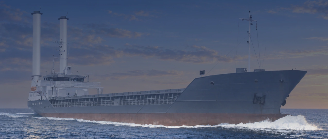
In 2023, two 17-metre suction sails were installed on the Eems Traveller. The sails, foundations and electrical connections were integrated into the existing configuration of the general cargo vessel.
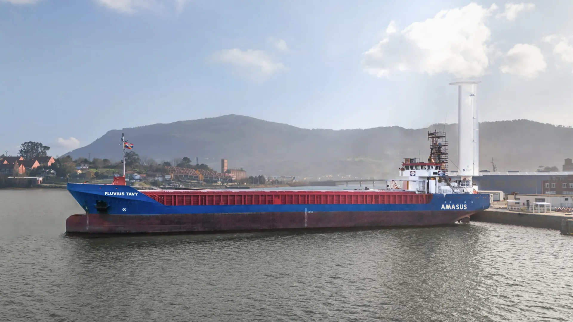
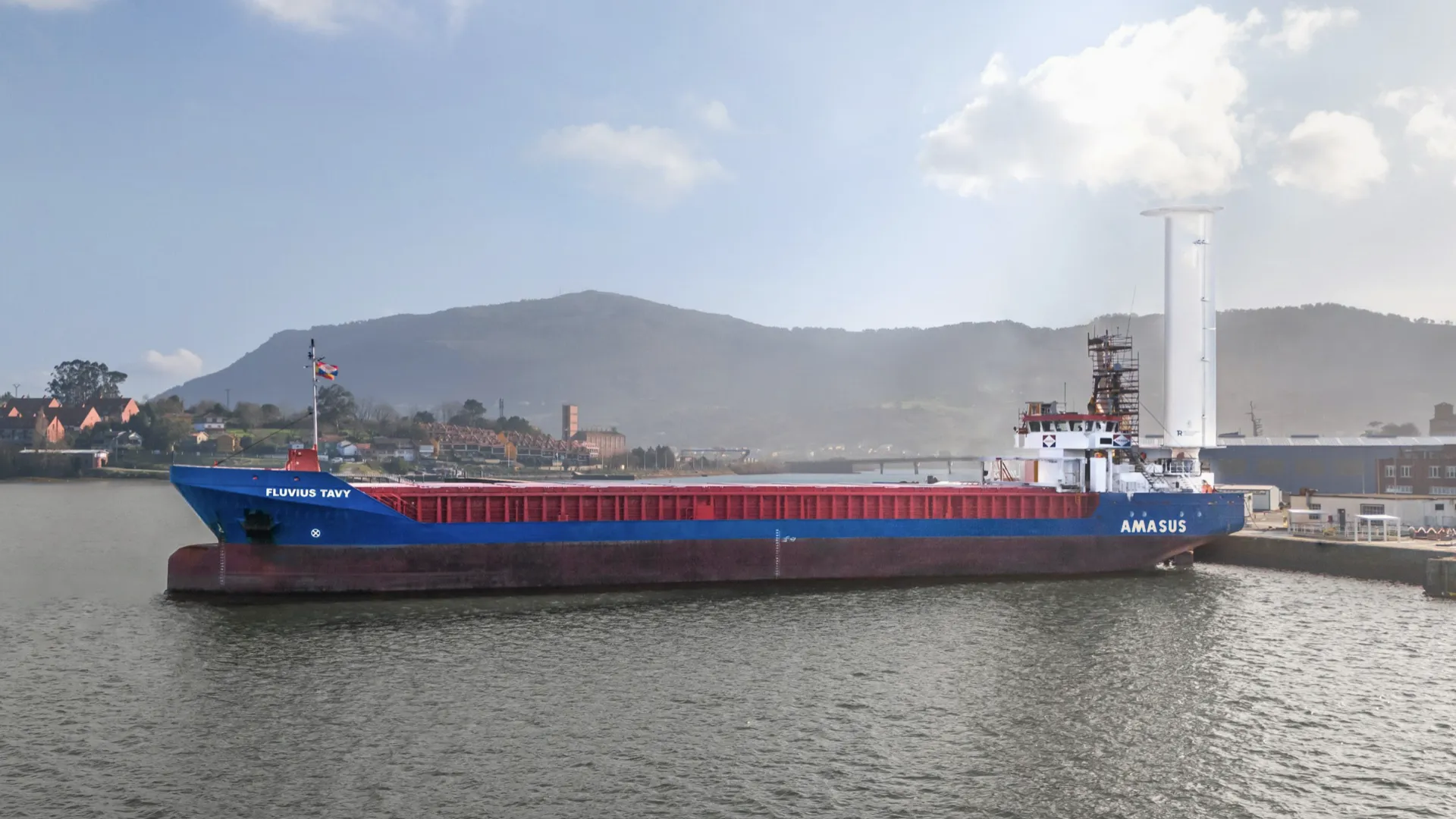
In December 2025, the Fluvius Tavy followed within the same fleet with a suction sail of 22 metres. This retrofit was carried out during scheduled maintenance at Astander Shipyard in Santander.
Our Approach to Selecting and Developing Suction Sail Arrangements
In the first project phase, possible combinations of model, height, number and position are investigated. The expected wind contribution is assessed alongside technical integration and operational use. Promising arrangements are compared on the same basis, so that performance and costs relate to the same configuration.
For the selected arrangement, foundations, reinforcements, electrical connections, control and maintenance access are developed further. The technical proposal describes which version and options are supplied, which components and work are included, and which additional assessments are required. The documentation and installation preparations are coordinated with the required approvals and vessel schedule.
Once the foundations and connections have been prepared, the suction sails can be installed and connected mechanically and electrically. During commissioning, the control system, sensors, operating modes, alarms and safe system positions are checked. Where performance verification forms part of the project, the reference data, measurement method and acceptance agreements are specified in advance. The operational data can then be used to track the net contribution and further adjust settings within permissible limits.
Contact Us About Suction Sails for Your Vessel
Are you considering suction sails for an existing vessel or a newbuild project? We would be pleased to discuss which arrangement may suit your operational profile and daily vessel operations. For a technical assessment, we would welcome a general arrangement plan, relevant deck plans and principal dimensions, together with information on loading conditions, stability and existing deck equipment.
Routes, seasonal use, hours at sea, usual vessel speeds and fuel or power data are important for the expected wind contribution. Available wind measurements and information on heading distribution can support the analysis. Please also specify any restrictions due to loading and unloading operations, ports, air draught and classified hazardous zones.
Information on deck structure, electrical load and available generator reserve helps assess integration. For retrofits, the planned docking or shipyard period and other intended vessel modifications are also relevant. During the project discussion, we agree which additional data are needed and how the technical and economic development can fit your schedule.
Discuss which suction sail configuration suits your vessel >
Retrofit Experience: Eems Traveller and Fluvius Tavy
In 2023, two 17-metre suction sails were installed on the Eems Traveller. The sails, foundations and electrical connections were integrated into the existing configuration of the general cargo vessel.
In December 2025, the Fluvius Tavy followed within the same fleet with a suction sail of 22 metres. This retrofit was carried out during scheduled maintenance at Astander Shipyard in Santander.